Q.(a) Explain the term 'sharpness of resonance' in ac circuit.
🔒You're viewing a preview — the full solution, concept, methods & PYQ mapping are locked.
🔒 Start your 14-day free trial to unlock the full solution →Part (a)Concept understanding — Resonance in AC Circuits
Resonance in AC Circuits
A series circuit containing a resistor R, an inductor L and a capacitor C driven by an AC source exhibits resonance — a sharp condition at which the circuit responds most strongly.
The Competing Reactances
In a series RLC circuit the inductor and capacitor oppose the current in opposite senses. Their reactances are
XL=ωL,XC=ωC1
where ω=2πf is the angular frequency. As frequency rises, XL grows while XC shrinks. The total impedance is
Z=R2+(XL−XC)2
The Resonance Condition
At one special frequency the two reactances become exactly equal and cancel:
XL=XC⇒ω0L=ω0C1⇒ω0=LC1
The corresponding resonant frequency is
f0=2πLC1
At this frequency the impedance falls to its minimum, Z=R (purely resistive), so the current reaches its maximum value
Imax=RVrms
Because the reactances cancel, the source voltage and current are exactly in phase — the power factor is 1 at resonance.
Physical Picture
At resonance energy sloshes back and forth entirely between the inductor's magnetic field and the capacitor's electric field, cycle after cycle. The source only has to make up the small amount of energy lost as heat in R. This is the electrical analogue of a swing pushed at its natural frequency: a small periodic drive builds a large oscillation.
Sharpness and the Q-factor
How sharply the current peaks around f0 is measured by the quality factor:
Q=Rω0L=R1CL
A large Q (small R) gives a tall, narrow resonance curve — the circuit is highly selective, responding to a very narrow band of frequencies. A small Q gives a broad, flat peak.
Why It Matters …
Why this formula?
Resonance in AC Circuits: Why the Key Formulas Hold
Resonance in an AC circuit occurs when the inductive reactance (XL) and capacitive reactance (XC) exactly cancel each other out. Let's build the understanding step-by-step.
1. The Core Condition for Resonance
Consider a series RLC circuit (resistor R, inductor L, capacitor C) driven by an AC voltage source V=V0sin(ωt).
The total impedance Z of the series combination is:
Z=R+j(XL−XC)
where:
- XL=ωL (inductive reactance)
- XC=ωC1 (capacitive reactance)
- j=−1
Why resonance happens:
The circuit "wants" to let maximum current flow. The opposition to current comes from both resistance and reactance. But reactance can be negative (capacitive) or positive (inductive). When they are equal in magnitude but opposite in sign, they cancel:
XL=XC
This is the fundamental condition — not a formula to memorize, but a logical consequence of impedance minimization.
2. Deriving the Resonant Frequency
From XL=XC:
ωL=ωC1
Multiply both sides by ω:
ω2LC=1
Thus:
ω0=LC1
Since ω=2πf, the resonant frequency in hertz is:
f0=2πLC1
Why this makes sense:
- A larger L or C means the circuit takes longer to "oscillate" — lower frequency.
- A smaller L or C means faster oscillations — higher frequency.
- The product LC controls the natural time scale of the circuit.
3. What Happens at Resonance — Key Consequences
(a) Impedance is Minimum (Purely Resistive)
At resonance, XL−XC=0, so:
Z=R+j(0)=R
Why: The reactive parts cancel, leaving only the resistance. The circuit behaves like a pure resistor.
(b) Current is Maximum
From Ohm's law for AC:
I=ZV
At resonance, Z=R (minimum possible), so current is maximum:
Imax=RV
Why: The opposition to current is smallest when reactance cancels.
(c) Voltage Across L and C Can Be Very Large
The voltage across the inductor:
VL=I⋅XL=RV⋅ω0L
The voltage across the capacitor:
VC=I⋅XC=RV⋅ω0C1
Since XL=XC at resonance, VL=VC in magnitude, but they are 180° out of phase — they cancel each other in the loop.
Why this is important:
If R is small, VL and VC can be many times larger than the source voltage V. This is called voltage magnification — a key concept for tuned circuits and filters.
--- …
Part (b)Concept understanding — AC Through a Capacitor
AC Through a Capacitor — From Intuition to the Exact Statement
Imagine a capacitor as a tiny, two-plate storage tank for charge. When you connect it to a DC battery, it charges up quickly and then blocks any further current — that's why a capacitor is an open circuit for steady DC. But AC is different: the voltage keeps reversing, so the capacitor never gets a chance to settle. It is constantly being charged, discharged, charged the other way, discharged again — and that motion of charge is an alternating current.
The key intuition: current flows because the voltage is changing. If the voltage were steady, no current would flow. The faster the voltage changes, the larger the current. This is the opposite of a resistor, where current depends on the voltage itself, not its rate of change.
The Mathematical Link
For a capacitor, the charge stored is Q=CV. Current is the rate of flow of charge: I=dQ/dt. So:
I=CdtdV
This single equation is the whole story. If the applied voltage is sinusoidal, say V=V0sin(ωt), then:
I=Cdtd[V0sin(ωt)]=CV0ωcos(ωt)
Now compare the two waveforms:
- Voltage: V0sin(ωt) — starts at zero, rises to peak.
- Current: CV0ωcos(ωt) — starts at its maximum value, then falls.
A cosine is a sine shifted forward by 90∘ (or π/2 radians). So the current reaches its peak a quarter-cycle before the voltage does. That is the famous result: in a purely capacitive circuit, current leads voltage by 90∘.
The phase relation: I leads V by 90∘ in a pure capacitor. Equivalently, V lags I by 90∘.
Why "Leads" and Not "Lags"?
Think physically. At the instant you first apply the AC voltage, the voltage is zero but rising fastest (the slope of sin is maximum at zero). A fast-changing voltage means a large current. So the current is already at its peak while the voltage is still near zero. That is the meaning of "leading" — the current's peak comes first.
Later, when the voltage reaches its peak, it is momentarily not changing (slope = 0), so the current drops to zero. The current is always ahead of the voltage by exactly one quarter-cycle.
The Limiting Factor: Capacitive Reactance
From the current expression above, the peak current is:
I0=ωCV0
This looks like Ohm's law if we define an effective resistance-like quantity:
XC=I0V0=ωC1
This XC is called capacitive reactance. It has units of ohms, but it is not a resistance — it does not dissipate energy. It merely limits the current by the capacitor's opposition to changes in voltage.
XC=ωC1=2πfC1
Key points about XC:
- It is inversely proportional to frequency. At high f, the voltage changes rapidly, so the current is large — low reactance. At low f, the voltage changes slowly, so the current is small — high reactance. At DC (f=0), XC→∞, which is the open-circuit behaviour you already know.
- It is also inversely proportional to capacitance C. A larger capacitor stores more charge per volt, so for the same voltage change it pushes more current — lower reactance.
The Complete Picture in One Table
| Property | Resistor | Capacitor |
|---|---|---|
| Relation | V=IR | I=CdV/dt |
Part (a)
Sharpness of resonance measures how sharply the current peaks around the resonant frequency ω0=LC1 in a series LCR circuit. It is measured by the quality factor
Q=Rω0L=R1CL=Δωω0.
A large Q (small R) gives a tall, narrow peak (small bandwidth Δω) — sharper resonance. …
Part (a): sharpness of resonance is quantified by the quality factor Q=ω0L/R (higher Q = narrower, sharper peak); with VL=VC the circuit is at resonance, so the power factor is 1.
Part (b): for a capacitor, I=ωCV0cosωt=I0sin(ωt+π/2) — the current leads the voltage by 90∘; V is a sine and I a cosine curve.
Part (a) — Sharpness of resonance and power factor
Sharpness of resonance. A series LCR circuit driven at ω0=1/LC has maximum current. How rapidly the current falls as the frequency moves off ω0 is its sharpness, quantified by the quality factor
Q=Rω0L=R1CL,Q=Δωω0,
where Δω is the bandwidth (half-power width). High Q (low R) ⇒ tall, narrow peak = sharp resonance; low Q ⇒ broad peak.
Power factor when VL=VC=VR. From the phasor relation V=VR2+(VL−VC)2, VL=VC gives V=VR, i.e. XL=XC — the resonance condition. Then Z=R and …
Showing the 12 most recent of 40 on this concept.
- CBSE 2026Set 55/1/11 markMCQQ.In a series LCR circuit, the voltage across the resistor, capacitor and inductor is 10 V each. If the capacitor is short circuited, the voltage across the inductor will be (A) 10 V (B) 52 V (C) 25 V (D) 102 V
›Reveal solutionSolution
In a series LCR circuit, when each component drops 10 V, the source voltage is 10 V (since VC and VL cancel) and the equal drops imply XL=XC=R. Shorting the capacitor leaves an RL circuit of impedance R2, so the current becomes I′=R210 and the inductor voltage is VL′=I′XL=210=52 V. The answer is (B).
Concept and intuition
The problem gives a series LCR circuit where the voltage across each element — resistor, capacitor, and inductor — is 10 V. That’s a strong clue: in a series circuit, the current is the same through all components, but the voltages are not in phase. The resistor voltage is in phase with current, the inductor voltage leads by 90°, and the capacitor voltage lags by 90°. So the three 10 V readings are phasor magnitudes, not simple arithmetic sums.
The key insight: if the capacitor is shorted, the circuit becomes a simple RL series circuit. The source voltage remains the same (it’s fixed by the supply), but the impedance changes. We need to find the new inductor voltage.
Step-by-step solution
1. Find the source voltage from the initial LCR condition.
In a series LCR circuit, the phasor sum of voltages across R, L, and C equals the source voltage Vs. Since VL and VC are opposite in phase (180° apart), they subtract. Given VR=VL=VC=10 V:
Vs=VR2+(VL−VC)2=102+(10−10)2=10 V
So the source supplies only 10 V. This makes sense: the inductor and capacitor voltages cancel exactly, so the source only “sees” the resistor drop.
TipThis cancellation is the hallmark of resonance in a series LCR circuit — at resonance, XL=XC, and the impedance is purely resistive. Here, VL=VC implies XL=XC, so the circuit is at resonance.
2. Determine the relationship between R and XL (or XC).
At resonance, the current is I=Vs/R=10/R. The voltage across the inductor is VL=IXL=(10/R)XL=10 V. Therefore:
R10XL=10⇒XL=R
So the inductive reactance equals the resistance. Similarly, XC=R as well. …
- CBSE 2026Set V11 markMCQQ.Power factor of a series LCR circuit is maximum when :(a) XL=XC(b) XC=0(c) XL>XC(d) XL<XC
›Reveal solutionSolution
- CBSE 2026Set A1 markMCQQ.In an ac circuit of capacitance the current from potential difference is (A) forward (B) backward (C) both are in same phase (D) none of these
›Reveal solutionSolution
In a pure capacitor the current leads the applied voltage by π/2, i.e. current is ahead (forward).
For a capacitor driven by V=V0sinωt, the charge is q=CV and the current is
I=dtdq=ωCV0cosωt=ωCV0sin(ωt+2π).
…
- CBSE 2026Set ANNUAL1 markQ.Write True or False: The quality factor is ω_r L / R.
›Reveal solutionSolution
True — for a series resonant circuit, Q = ω_r L / R.
The quality factor (Q-factor) of a series resonant LCR circuit measures the sharpness of resonance. It is defined as the ratio of the inductive reactance at resonance to the resistance:
Q = ω_r L / R = (1/R)√(L/C),
…
- CBSE 2026Set SEM31 markMCQQ.The condition of getting maximum current in an LCR series circuit is(a) X_L = 0(b) X_C = 0(c) X_L = X_C(d) R = X_L − X_C
›Reveal solutionSolution
A series LCR circuit carries maximum current at resonance, where the inductive and capacitive reactances are equal (X_L = X_C), leaving impedance Z = R minimum. Option (c).
Step 1 — impedance of a series LCR circuit: Z = √(R² + (X_L − X_C)²), from NCERT/CBSE Class 12 Physics, Alternating Current.
…
- CBSE 2025Set D1 markMCQQ.In an a.c. circuit containing only capacitor, the phase difference between current and voltage is (A) 0° (B) 90° (C) 180° (D) 45°
›Reveal solutionSolution
In a pure capacitor the current leads the applied voltage by a quarter cycle, i.e. a phase difference of 90°.
For an a.c. circuit containing only a capacitor, the charging current is maximum when the voltage is zero and vice versa. The current leads the voltage by
…
- CBSE 2025Set D1 markMCQQ.In resonance condition, the frequency of L-C circuit is (A) (1/2π)√(1/LC) (B) 2π√(1/LC) (C) 2π√(LC) (D) (1/2π)√(LC)
›Reveal solutionSolution
At resonance the inductive and capacitive reactances are equal, giving the natural frequency f = 1/(2π√(LC)).
Resonance in an L-C (or series L-C-R) circuit occurs when the inductive reactance equals the capacitive reactance:
XL=XC ⇒ ωL=ωC1
Solving for the angular frequency,
…
- CBSE 2025Set ANNUAL1 markQ.Draw the phasor diagram to represent current and supply voltage for an AC circuit containing capacitance only.
›Reveal solutionSolution
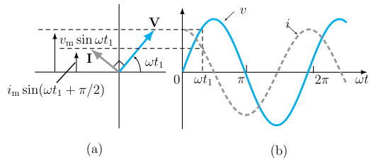
Figure — Explicit 'Draw the phasor diagram ... AC circuit containing capacitance only' hard gate. Catalog fig-7-8 is ex In a pure capacitor, I leads V by π/2.
In an AC circuit containing only a capacitor, the current leads the applied voltage by a phase angle of 90° (π/2 radians) — this follows from I=CdtdV, since the current is proportional to the rate of change of voltage, which is largest when V is crossing zero and zero when V is at its peak. In the phasor diagram, the voltage phasor V0 is drawn along the reference (horizontal) axis, and the current phasor I0 is drawn rot …
- CBSE 2025Set ANNUAL1 markMCQQ.A series LCR circuit fed by an ac source with angular frequency ω acts as a purely resistive circuit, when(a) ωL > 1/ωC(b) ωL < 1/ωC(c) ωL = 1/ωC(d) ω³L = 1/ωC²
›Reveal solutionSolution
A series LCR circuit behaves as purely resistive at resonance, when the inductive and capacitive reactances cancel.
The impedance of a series LCR circuit is
Z=R2+(ωL−ωC1)2 …
- CBSE 2025Set ANNUAL1 markMCQQ.When LCR series circuit is at resonance then the phase angle (phi) between current and voltage is –(a) pi/2(b) pi(c) 2 pi(d) 0
›Reveal solutionSolution
At resonance in a series LCR circuit, current and voltage are exactly in phase.
In a series LCR circuit, the phase angle ϕ between the applied voltage and current is given by tanϕ=RXL−XC, where XL=ωL and XC=ωC1.
…
- CBSE 2025Set ANNUAL1 markMCQQ.The power delivered by the AC source of a circuit becomes maximum when(i) wL = wC(ii) wL = 1/(wC)(iii) wL = -(1/(wC))^2(iv) wL = sqrt(wC)
›Reveal solutionSolution
Maximum power occurs at resonance, wL = 1/(wC).
In a series LCR circuit the impedance is Z=R2+(XL−XC)2 with XL=ωL and XC=1/ωC. Power P=VrmsIrmscosϕ is greatest when Z is minimum (Z = R) and the current is in phase with the voltage. …
- CBSE 2024Set A11 markMCQQ.The resonance phenomenon is exhibited by a circuit only if following components are present(a) L and R(b) R and C(c) L and C(d) None of the above
›Reveal solutionSolution
🎓Unlock everything free for 14 days
- ✓Full step-by-step solutions
- ✓Concept-first explanations
- ✓Methods, shortcuts & mistakes
- ✓PYQ mapping + timed mock tests
Full access for 14 days. No credit card required.