Physics · Ch 8 — Electrostatics
Capacitance of a Parallel Plate Capacitor With a Dielectric Slab Between the Plates
Capacitance of a Parallel Plate Capacitor With a Dielectric Slab Between the Plates
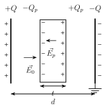
Now insert a dielectric slab of thickness t (with , so it fills only PART of the gap, in general) between the two plates. BEFORE the slab is inserted, the field in the gap is (from section 8.10.1) and the potential difference is .
Once the slab is inserted, the applied field polarises it (section 8.8), inducing a layer of charge on the slab's near face and on its far face; these induced surface charges themselves set up an internal POLARISATION field that points OPPOSITE to , so the NET field actually present inside the dielectric material is the difference, . Writing this reduction using the dielectric constant as (the definition already established in section 8.8) lets itself be expressed as .
Because the reduced field exists only across the slab's own thickness t, while the FULL, undiminished field still exists across the remaining air gap of thickness , the total potential difference across the WHOLE plate separation becomes . The resulting capacitance, with the slab in place, is therefore -- always GREATER than the bare , since for any real dielectric makes the effective denominator smaller than alone. …
Drawn by us to help you understand the concept clearly, and verified to make sure it's accurate. For exams, practice from your textbook's own diagram.
What this figure shows. A parallel plate capacitor with plates separated by distance d, and a dielectric slab of thickness (with ) inserted between them, occupying only part of the gap; the applied field is drawn as arrows spanning the full gap, while inside the slab itself a shorter, oppositely-directed arrow for the induced polarisation field is drawn, together with the induced surface charge layers and marked on the slab's own near and far faces respectively -- the geometric set-up for deriving both the reduced net field inside the dielectric and t …
Drawn by us to help you understand the concept clearly, and verified to make sure it's accurate. For exams, practice from your textbook's own diagram.
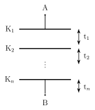
What this figure shows. A parallel plate capacitor whose full gap between the plates is filled with distinct dielectric slabs stacked one after another (like layers), each of its own thickness (summing to the total plate separation ) and its own dielectric constant -- the layered picture used to justify treating such a stack as capacitors in SERIES, one per slab, each contributing its own term to the combin …
Worked out. A parallel plate capacitor has plate area and separation m. (i) Without a dielectric: F. (ii) With the gap COMPLETELY filled by a dielectric of constant : F -- a direct before/after comparison showing the capacitance rising by exactly the factor once the dielectric fully occupies the gap, exactly matching special case (1) de …
Worked out. A capacitor of has plates m apart. A dielectric slab of thickness m and constant is inserted (occupying only HALF the gap). Using and dividing by the original : , so -- the capacitance rises, but by LESS than the full factor of , since the dielectric here fills only half …