Physics · Ch 16 — Semiconductor Devices
NOT Gate
NOT Gate
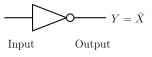
The NOT gate is the most basic logic gate of all: it has exactly ONE input and ONE output, and simply produces the NEGATED (inverted) version of whatever is applied at its input -- if the input is 0 (low), the output is 1 (high); if the input is 1 (high), the output is 0 (low). Because of this behaviour, the NOT gate is also commonly called an INVERTER. Its Boolean expression is written , where the overline denotes logical negation ('NOT X'); its circuit symbol (Fig. 16.27) is a triangle followed by a small circle ('bubble') at its output tip, the bubble …
Drawn by us to help you understand the concept clearly, and verified to make sure it's accurate. For exams, practice from your textbook's own diagram.
What this figure shows. A single triangle pointing to the right, representing an amplifier/buffer stage, with a single input line entering the flat (left) side of the triangle and a single output line leaving its pointed (right) vertex; at the output vertex, a small open CIRCLE ('bubble') is drawn touching the tip of the triangle -- this small circle at the output is the standard symbol that specifically denotes logical inversion/negation, distinguishing the NOT gate's symbol from a plain (non-inverting) buffer …
Input X | Output Y
0 | 1 …