Physics · Ch 16 — Semiconductor Devices
OR Gate
OR Gate
The OR gate has two (or more) inputs and a single output, and represents what is sometimes called LOGICAL ADDITION. Its output Y is 1 (high) whenever ANY ONE of its inputs is 1, or when more than one input (or all of them) are 1 simultaneously -- in other words, Y is 0 (low) in exactly the single case where EVERY input is 0. For the standard two-input case, its Boolean expression is (Fig. 16.28), where the '+' symbol here denotes the logical OR operation, not ordinary arithmetic addition (so $ …
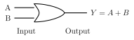
Drawn by us to help you understand the concept clearly, and verified to make sure it's accurate. For exams, practice from your textbook's own diagram.
What this figure shows. A curved, shield- or D-shaped body with a distinctly CONCAVE (curved-inward) flat/back edge on the input side and a POINTED, curved-outward tip on the output side -- the standard OR-gate shape. Two separate input lines (A and B) enter the concave back edge from the left, and a single output line (labelled ) leaves the pointed tip on the right -- this curved-back, pointed-front outline is what visually distinguishes an OR gate from an A …
Input A | Input B | Output Y
0 | 0 | 0
0 | 1 | 1 …