Q.Draw the circuit diagram for a full wave rectifier using p-n junction diode. Explain its working principle and show the input-output waveforms. (1+1+1) OR With the help of a circuit diagram, explain the use of Zener diode as a voltage stabilizer. (1+2)
You're viewing a preview — the full solution, concept, methods & PYQ mapping are locked.
Start your 14-day free trial to unlock the full solution →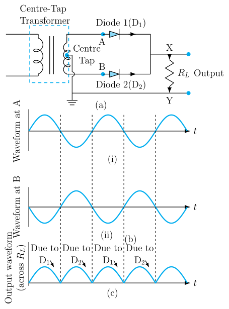
Two diodes connected to opposite ends of a centre-tapped transformer secondary conduct on alternate half-cycles, so the load always receives current in the same direction, turning both halves of the AC waveform into pulsating DC.
Circuit (described): A centre-tapped transformer secondary has its centre tap connected to one terminal of the load (through ground/common), while its two end terminals are each connected to the anode of a diode ( and ). The cathodes of both diodes are joined together and connected to the other terminal of the load .
Working principle: The AC input is applied to the primary of the transformer. Because of the centre tap, the voltages at the two ends of the secondary winding are equal in magnitude but opposite in phase relative to the centre tap at every instant.
- During the half-cycle when the upper end of the secondary is positive relative to the centre tap, diode becomes forward biased and conducts, while (whose end is negative) is reverse biased and does not conduct. Current flows through and the load.
- During the next half-cycle, the polarity reverses: the lower end becomes positive, so conducts while is reverse biased. Current again flows through the load, in the same direction as before (because of how the diodes and centre tap are arranged).
Since current flows through in the same direction during both halves of the input cycle, the output is a series of unidirectional pulses at twice the input frequency — this is full-wave rectification.
…
Unlock everything free for 14 days
- Full step-by-step solutions
- Concept-first explanations
- Methods, shortcuts & mistakes
- PYQ mapping + timed mock tests
Full access for 14 days. No credit card required.