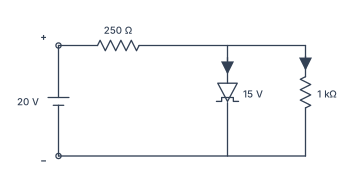
Q.Give reason to explain why n and p regions of a Zener diode are heavily doped. Find the current through the Zener diode in the circuit given below : (Zener breakdown voltage is 15 V)
You're viewing a preview — the full solution, concept, methods & PYQ mapping are locked.
Start your 14-day free trial to unlock the full solution →The Zener diode's heavy doping creates a thin depletion layer, enabling a sharp breakdown at a low voltage. In the given circuit, the Zener current is found by subtracting the load current from the total series current, giving 5 mA.
Why heavy doping in Zener diodes?
The n and p regions of a Zener diode are deliberately made much more heavily doped than ordinary p-n junction diodes. This is the key design choice that makes Zener breakdown possible at a low, precisely controlled voltage.
When doping levels are high, the number of charge carriers (electrons and holes) available for recombination at the junction is large. As a result, the depletion region — the zone depleted of free carriers — becomes very thin, typically just a few nanometres wide. A thin depletion layer means that even a modest reverse-bias voltage creates an extremely high electric field across it (since field strength = voltage / distance). This intense field is strong enough to directly pull electrons out of their covalent bonds in the depletion region, a process called Zener breakdown. The breakdown occurs at a sharply defined voltage (here, 15 V) and the diode can safely conduct in reverse without being destroyed, as long as the current is limited by an external resistor.
A common mistake is to think Zener diodes break down because of avalanche multiplication (like ordinary diodes at high reverse voltage). That's wrong — Zener breakdown is a field-emission effect, not an impact-ionisation effect. The heavy doping is what makes the field strong enough for this to happen at low voltages.
Finding the Zener current in the circuit
The circuit is a simple Zener shunt regulator: a 20 V DC supply, a 250 Ω series resistor, a Zener diode (breakdown 15 V), and a 1 kΩ load resistor all in parallel with the Zener.
Step 1: Recognise the operating condition.
Since the supply voltage (20 V) exceeds the Zener breakdown voltage (15 V), the Zener diode will break down and regulate the voltage across itself — and therefore across the load — at a constant 15 V. This is the fundamental behaviour of a Zener regulator: the diode "clamps" the voltage.
Step 2: Find the total current from the supply.
The series resistor drops the excess voltage. The voltage across it is:
Using Ohm's law, the total current flowing through (which then splits between the Zener and the load) is: …
Unlock everything free for 14 days
- Full step-by-step solutions
- Concept-first explanations
- Methods, shortcuts & mistakes
- PYQ mapping + timed mock tests
Full access for 14 days. No credit card required.