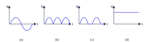
Q.With the help of a circuit diagram, explain the working of a p-n junction diode as a full wave rectifier. Draw its input and output waveforms.
You're viewing a preview — the full solution, concept, methods & PYQ mapping are locked.
Start your 14-day free trial to unlock the full solution →A full-wave rectifier uses two p-n junction diodes with a centre-tapped transformer. The diodes conduct alternately — one in each half-cycle — but both drive current through the load in the same direction, converting the full AC cycle into pulsating DC. The output ripple frequency is and the average output voltage is .
The Concept: Why Full-Wave Rectification?
A p-n junction diode conducts only when forward-biased (p-side positive, n-side negative) and blocks current when reverse-biased. This one-way valve property makes it perfect for rectification — converting alternating current into direct current.
In half-wave rectification, we waste half the AC cycle by blocking it entirely. Full-wave rectification is smarter: it makes the negative half-cycle also contribute, so both halves of the AC input deliver current to the load. The result is a higher average output voltage, less ripple, and better utilisation of the transformer.
The centre-tapped transformer design achieves this elegantly by providing two secondary voltages that are out of phase with each other. While one diode conducts during the positive half-cycle of its input, the other conducts during what would have been the negative half-cycle — which, from its own end of the winding, is a positive half-cycle.
The Circuit
The circuit consists of:
- A transformer whose primary coil is connected to the AC mains.
- A centre-tapped secondary with three terminals: the two ends A (top) and B (bottom), and the centre tap C.
- Two diodes: the anode of is connected to end A and the anode of to end B. Their cathodes are joined together and connected to one terminal of the load resistor .
- The other terminal of returns to the centre tap C, which serves as the common reference.
Because C is the midpoint of the winding, the instantaneous voltages of A and B measured from C are always equal in magnitude and opposite in sign: if , then .
Working Principle: Step-by-Step
1. The centre tap creates two anti-phase voltages
The centre-tapped secondary effectively gives us two AC sources of equal magnitude and opposite polarity, sharing the common terminal C.
2. During the positive half-cycle of the input (0 to )
When terminal A is positive with respect to C:
- Diode is forward-biased (its anode at A is positive) and conducts.
- Diode is reverse-biased (its anode at B is negative relative to C) and blocks.
- Current flows along the path A → → load → C.
- The load receives a positive half-sine pulse of voltage.
3. During the negative half-cycle of the input ( to )
When terminal A swings negative with respect to C, terminal B becomes positive:
- Diode is now reverse-biased and blocks.
- Diode is forward-biased and conducts.
- Current flows along the path B → → load → C.
- The load still receives current in the same direction — from the joined cathodes toward the centre tap.
4. The key result: unidirectional current
In both half-cycles, current through the load flows in the same direction. The load simply receives one positive half-sine pulse after another — pulsating DC.
The key insight is that the centre tap acts as a reference point. Both diodes deliver current to the load in the same direction relative to this reference, even though they conduct alternately.
5. Output characteristics
- Frequency: the output ripple frequency is , where is the input AC frequency — each input cycle produces two output pulses.
- Average DC voltage: , where is the peak secondary voltage measured from the centre tap to either end. …
Unlock everything free for 14 days
- Full step-by-step solutions
- Concept-first explanations
- Methods, shortcuts & mistakes
- PYQ mapping + timed mock tests
Full access for 14 days. No credit card required.