Electronics · Ch 8 — Modulation and Demodulation
Demodulation
Demodulation
Demodulation, also called detection, is the process of recovering the original modulating (baseband) signal from a modulated carrier wave. It is exactly the reverse of modulation: at the transmitter the message is impressed on a high-frequency carrier, and at the receiver that message must be pulled back out. The circuit or device that does this recovery is called a detector or demodulator. This stage sits at the heart of the receiver in any Karnataka 2nd PUC Electronics communication system, and it is a favourite topic in the II PUC board exam.
Why demodulation is necessary
The wave that reaches the receiving antenna carries the audio information riding on a radio-frequency (RF) carrier. This composite wave cannot be fed straight to a loudspeaker, for two reasons. First, the speaker's diaphragm has appreciable inertia and cannot vibrate fast enough to follow an RF signal — at such high frequencies it would not move at all, so no sound would be heard. Second, the carrier frequency lies far above the range the human ear can hear. The audio component must therefore be separated from the RF carrier before it can be reproduced as sound.
The two jobs of a detector
A detector performs two tasks:
- Rectification of the modulated wave. An AM wave has positive and negative peaks of equal amplitude, so its average value over a cycle is zero. A loudspeaker cannot respond to a net-zero current, so the wave is first rectified — usually with a simple diode — to keep only one half of each cycle.
- Separation of the audio signal from the carrier. The rectified wave still contains both the modulating signal and the high-frequency carrier. A capacitor filter bypasses (removes) the RF portion, leaving the low-frequency modulating signal, which is passed on to the speaker.
Types of AM detector
For amplitude-modulated signals, detectors fall into two classes:
- Square-law detectors, used for low-level modulated signals (below about 1 V), where the device is biased to work in the non-linear (square-law) region of its characteristic.
- Envelope (diode) detectors, used when the AM signal has a large carrier. The envelope detector is the simplest and most widely used AM demodulator.
Diode (envelope) detector
An envelope detector uses a diode operating in the linear region of its characteristic (above about 1 V) to trace out the envelope of the AM wave. A parallel LC 'tank' circuit at the input acts as the tuned circuit: by varying the capacitor C the resonant frequency is changed, so a station of any desired frequency can be tuned in. When the selected modulated signal is applied, the diode conducts only on the positive half-cycles and blocks the negative half-cycles, so only the positive envelope of the carrier appears across the R1-C1 network.
The R1-C1 combination forms a low-pass filter that removes the residual RF. Its time constant is chosen to be short compared with the radio-frequency period but long compared with the audio period: on each positive peak the diode conducts and charges C1 rapidly through the diode's small forward resistance; when the diode is off, C1 discharges slowly through the large resistance R1. The capacitor voltage therefore follows the envelope of the modulated carrier. The recovered output is slightly spiky because of this repeated charge-discharge, but it almost exactly traces the envelope; the spikes are minimised by a suitable choice of R1, C1 and depth of modulation. Finally, a coupling capacitor CB blocks the steady DC level; that DC component is proportional to signal strength and is commonly tapped off for automatic gain control (AGC). …
The process of recovering the original modulating (baseband) signal from a modulated carrier wave — the exact reverse of modulation. The device that performs it is called a detector or demodulator. It is needed because a loudspeaker cannot follow a radio-frequency wave, so the detector must both rectify the modulated wave and …
An AM demodulator in which a diode operating in the linear region of its characteristic (above about 1 V) extracts the envelope of the AM wave. A tuned LC tank selects the station; the diode passes only positive half-cycles; and an R1-C1 low-pass filter (short time constant at audio, long at RF) recovers the envelo …
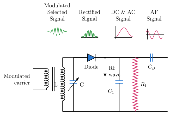
Drawn by us to help you understand the concept clearly, and verified to make sure it's accurate. For exams, practice from your textbook's own diagram.
Textbook Figure 8.6.1 (Diode detector). The modulated carrier is coupled through a transformer into a parallel LC tank (L with a variable capacitor C) that tunes to the wanted station. The diode (anode on the tank side) conducts only on positive half-cycles; a shunt R1-C1 low-pass network then filters off the RF, leaving the envelope, and a series coupling capacitor CB blocks the DC before the AF output. Small waveforms along the top show the selected modulated signal, the rectified signal, the DC-plus-AC signal …