Electronics · Ch 8 — Modulation and Demodulation
Modulation by Several Sine Waves
Modulation by Several Sine Waves
In practice a carrier is rarely modulated by a single pure tone. A real information signal — speech, music, video — contains many frequencies at once, so the carrier is modulated simultaneously by several sinusoidal modulating signals of different frequencies. When this happens, the individual modulation indices combine as the root of the sum of their squares:
where are the modulation indices for the different modulating signals. As always, the total modulation index should not exceed unity, otherwise the wave is over-modulated and distortion results.
Types of Amplitude Modulation
Because the high-frequency spectrum is a limited resource, communication systems try to use the minimum possible bandwidth. An ordinary AM signal occupies a bandwidth of , and at 100% modulation about 67% of the total power goes into the carrier, which carries no information. Moreover, each sideband is an exact image of the other, so one sideband can be suppressed without any loss of information. These facts lead to several economical forms of AM:
- Double Side Band Suppressed Carrier (DSB-SC) — the carrier is removed and only the two sidebands are transmitted. About of the total transmitted power is saved for . It is used in FM and TV broadcasting to transmit two-channel stereo signals.
- Single Side Band Transmitted Carrier (SSB-TC) — one sideband is suppressed while the carrier and the other sideband are transmitted. About of the total power is saved for .
- Single Side Band Suppressed Carrier (SSB-SC or simply SSB) — both one sideband and the carrier are suppressed, so only a single sideband is transmitted. About of the total power is saved for .
Advantages, disadvantages and applications of SSB-SC
Advantages: it saves about 83.33% of the power; selective fading is largely absent; operating cost is lower; interference from noise is reduced; bandwidth limiting gives roughly 10–12 dB of noise reduction; it is efficient overall; it needs a smaller power supply; and because its bandwidth is halved, more stations can be accommodated in a given band.
Disadvantages: generation and reception of an SSB signal are complicated; the transmitter and receiver are more complex and expensive; and SSB is not suited to high-quality music, being used mainly for speech.
Applications: owing to its complexity and cost SSB-SC is not used for commercial broadcasting, but is used in land and mobile communication, telemetry, military communications, navigation, amateur radio and point-to-point speech communication.
Generation of AM signals
An AM signal is generated by combining the carrier and the baseband signal through a non-linear device. The circuit that does this is called an amplitude modulator — it superimposes the low-frequency modulating signal on the high-frequency carrier so that the carrier amplitude varies with the instantaneous value of the modulating signal. Amplitude modulators are of two kinds:
- Low-level modulators generate AM using a small signal, which must then be amplified before transmission.
- High-level modulators produce AM at high power levels, usually in the final stage of the transmitter.
Collector modulator
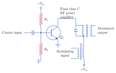
The collector modulator (Figure 8.4.1) is an example of a high-level modulator. It is named a collector modulator because the modulating signal is injected into the collector circuit of the transistor. It consists of a radio-frequency amplifier operated in class C mode, in which the transistor conducts only for a small portion of the positive half-cycle of the input. Resistors R1 and R2 form a voltage-divider bias for the base. The LC tank circuit in the collector is tuned to resonate at the carrier frequency; being high-impedance at resonance, it makes the carrier frequency available at the output. The signal to be modulated is coupled in through transformer T1, whose secondary winding places the modulating signal in series with the collector supply , so that the collector current amplitude varies with the modulating signal.
Operation: as the audio signal drives the primary of T1, a voltage is induced across the secondary that adds to or subtracts from depending on its instantaneous polarity. The collector supply is therefore no longer constant; as it changes, the Q-point and current-pulse amplitude of the transistor change with it. These current pulses excite the tuned circuit into oscillation at the carrier frequency, producing across the tank a sinusoidal RF voltage whose peak amplitude follows the modulating signal — an amplitude-modulated wave. Its advantages are very good linearity, high circuit efficiency and high power output; its disadvantages are that the modulating-power requirement is very high, and that because of the transistor's non-linear response to small signals, 100% modulation cannot quite be achieved.
AM transmitters
An AM transmitter performs the modulation and raises the power level so the signal can be radiated effectively; it handles speech and music and is used in the medium-wave and short-wave bands. The AM band runs from 535 kHz to 1605 kHz and the short-wave band from 3 MHz to 30 MHz, typically handling audio frequencies up to about 5 kHz. AM transmitters are built with either high-level modulation or low-level modulation.
High-level versus low-level modulation
The two types differ in where the carrier and modulating signals are power-amplified. In low-level modulation, modulation takes place before the output element of the final stage, so less power is needed to reach a high percentage of modulation; a class A amplifier is used for the low-level modulator. In high-level modulation, modulation takes place in the final element of the final stage, where the carrier is already at maximum amplitude, so a much larger modulating signal is needed; a class C amplifier is used. …
(8.26), where are the modulation indices of the individual modulating signals. The total must not exc …
A form of AM in which the carrier is removed and only the two sidebands are transmitted, saving about two-thirds of the total power at 100% modulation. Used in FM and TV broadcastin …
A form of AM in which both the carrier and one sideband are suppressed and only a single sideband is transmitted, saving about five-sixths (≈83.33%) of the power. Complex and costly, so used for point-to-point speech, mobile, military and amat …
Drawn by us to help you understand the concept clearly, and verified to make sure it's accurate. For exams, practice from your textbook's own diagram.
Figure 8.4.1 (Collector modulator): an NPN transistor Q1 as a final class C RF power amplifier with a divider bias (R1, R2), the carrier fed to the base and the modulating signal introduced through transformer T1 in series with the collector supply ; a collector LC tank tuned to the carrier …
Drawn by us to help you understand the concept clearly, and verified to make sure it's accurate. For exams, practice from your textbook's own diagram.
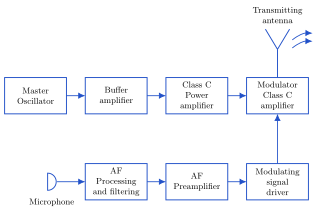
Figure 8.4.2 (Block diagram of high level AM transmitter): an RF chain (master oscillator → buffer amplifier → class C power amplifier → class C modulator → transmitting antenna) and an audio chain (microphone → AF processing and filtering → AF preamplifier → modulating-signal driver) that feeds the modul …