Electronics · Ch 8 — Modulation and Demodulation
Digital communication
Digital communication
In digital communication, information is encoded as discrete (digital) signals — sequences of 1s and 0s — and transferred electronically to the recipient. It is one of the commonest modes of communication today. The information flows in digital form (the source is often simply a computer keyboard), a single person can operate it, and it is among the cheapest and fastest modes — a message can reach its destination in a fraction of a second — as well as being reliable.
Analog and digital communication differ in several ways, summarised in the table below: an analog signal varies continuously through infinitely many values, whereas a digital signal takes only a finite set of discrete values; analog systems use modulation schemes such as AM, FM, PAM and PWM, while digital systems use PCM; analog circuitry is simpler but slower, noisier and needs less bandwidth, while digital circuitry is more complex but faster, far less noisy and more efficient, at the cost of larger bandwidth.
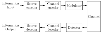
Block diagram of a digital communication system
The signal passes through the following blocks (Figure 8.10.1):
Information input -> Source encoder -> Channel encoder -> Modulator -> Channel -> Detector -> Channel decoder -> Source decoder -> Information output.
- Source encoder — converts the information into binary code (digitising it if the input is an analog waveform).
- Channel encoder — generates a channel code word from the source code words, adding structure that guards against troublesome bit patterns and errors on the channel.
- Modulator — converts the channel code words into a continuous wave suitable for the transmission channel.
- Channel — the medium that carries the signal to the receiver. …
| Analog communication | Digital communication |
|---|---|
| A continuously varying signal with an infinite number of values | Signals represented by a finite set of discrete values |
| The information signal transmitted is analog in nature | Information of any form is converted into a digital signal and transmitted as 1s and 0s |
| Uses AM, FM, PAM, PWM types of modulation | Uses PCM, where information is converted into a series of numbers/digits |
| Needs simple circuitry | Needs complex circuitry |
Drawn by us to help you understand the concept clearly, and verified to make sure it's accurate. For exams, practice from your textbook's own diagram.
Textbook Figure 8.10.1 (Block diagram of digital communication system). Top row left to right: Information input, Source encoder, Channel encoder, Modulator, then down into a Channel block on the right. Bottom row right to left: Detector, Channel decoder, Source decoder, Information output. It gro …