Electronics · Ch 8 — Modulation and Demodulation
Functions of a radio receiver
Functions of a radio receiver
A radio receiver is the equipment that picks up the modulated radio wave from the antenna and turns it back into sound. Its main functions are to: (1) intercept the incoming modulated signal; (2) select the desired station from the many carrier frequencies present; (3) amplify that selected modulated carrier; (4) separate the modulating signal from the carrier by detection; (5) amplify the recovered audio-frequency signal; and (6) convert the audio signal into sound.
Receiver characteristics
The quality of a receiver is judged by five characteristics:
- Sensitivity — the ability to respond to a weak signal, measured as the minimum input voltage (or power) needed to give a specified output, usually expressed in microvolts. A typical AM broadcast receiver has a sensitivity of about 50 microvolts. It depends on the overall voltage gain and the signal-to-noise ratio.
- Selectivity — the ability to pick out the wanted station and reject all others. It is set by the bandwidth of the tuned circuit, which depends on its quality factor : a higher Q gives a narrower bandwidth and hence sharper selectivity and better rejection of unwanted signals.
- Fidelity — the ability to reproduce at the output, faithfully, the signal present at the input. It depends on the bandwidth of the audio amplifier that handles the modulating signal.
- Signal-to-noise ratio (S/N) — the ratio of output signal power to output noise power, . A higher S/N means better performance; an S/N of about 40 dB is needed for satisfactory broadcast reception.
- Stability — the ability to stay tuned to a chosen frequency and deliver a constant output over long periods and varying conditions, without repeated re-tuning. Instability is caused mainly by supply-voltage and temperature variations.
The superheterodyne receiver
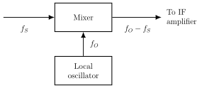
Almost every modern receiver uses the superheterodyne principle. Instead of amplifying each incoming station at its own frequency, the receiver converts every incoming carrier down to one fixed, lower frequency — the intermediate frequency (IF) — using a local oscillator whose frequency is kept a fixed amount above the incoming carrier. Because all stations are then handled at the same IF, the amplifier stages can be optimised once for excellent, uniform selectivity and gain. In commercial AM receivers the IF is fixed at 455 kHz.
Heterodyne action is the mixing (beating) of two signals of different frequency to produce new frequencies — the sum and the difference of the two inputs. If a carrier is mixed with a local-oscillator signal , the mixer produces and ; the sum is filtered out and the difference is the IF. For example, an AM carrier at 1000 kHz mixed with a local oscillator at 1455 kHz produces 2455 kHz and 455 kHz; the 2455 kHz is removed, leaving the 455 kHz IF.
Stages of the AM superheterodyne receiver
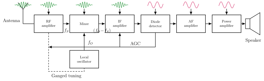
- RF section — a tuned filter and voltage amplifier that selects the wanted frequency band and amplifies the weak RF signal with a good signal-to-noise ratio before passing it to the mixer.
- Mixer — a non-linear stage that converts the incoming carrier down to the fixed 455 kHz IF. Its local oscillator is tuned exactly 455 kHz above the carrier, i.e. . The RF and oscillator tuning capacitors are ganged, so one knob keeps this constant difference.
- Local oscillator — a sine-wave generator, commonly a Hartley (or Colpitts) oscillator; the Hartley is popular because it is easier to tune by varying capacitance than inductance.
- IF amplifier — two or more tuned stages at 455 kHz that provide most of the receiver's gain and the bulk of its selectivity, passing signals within the IF band and rejecting the rest.
- Detector — usually a diode detector, chosen for low distortion and good fidelity; it removes the negative half-cycles, filters off the RF, and recovers the modulating signal.
- AF amplifier — an RC-coupled voltage amplifier that raises the weak detector output to a level able to drive the power stage.
- Power amplifier — a push-pull power amplifier (bandwidth at least about 5 kHz) that feeds the loudspeaker through an impedance-matching transformer, reproducing the original sound.
Automatic Gain Control (AGC)
As the receiver is tuned across stations, or as reception conditions change, the received signal strength varies, which would make the output level jump about. AGC (also called AVC, automatic volume control) is a feedback arrangement that samples a fraction of the detector output and turns it into a bias voltage — large for strong signals, small for weak ones. This bias is fed back to the RF amplifier, mixer and IF amplifier to reduce their gain on strong signals, holding the IF carrier level, and hence the output, roughly constant.
Choice of intermediate frequency
The IF value is a compromise, because both very low and very high IFs bring problems. A low IF improves selectivity but makes image interference harder to reject, and if it is too low the response becomes so sharp that sidebands are cut. A very high IF reduces selectivity, adjacent-channel rejection and gain, and can cause tracking difficulties between the signal and oscillator circuits. The IF must also not fall within the receiver's own tuning range, or heterodyne interference and instability result. Typical IF values by receiver type are listed in the table below.
Choice of local-oscillator frequency
Since the mixer forms both sum and difference frequencies, the 455 kHz IF could in principle be obtained with the oscillator either above or below the signal. In practice the oscillator is always kept above the signal. For the medium-wave band (550-1650 kHz) with a 455 kHz IF, an oscillator above the signal must tune from (550+455) to (1650+455) kHz, needing a capacitance ratio
which ordinary ganged capacitors (about 10:1) handle easily. If the oscillator were kept below the signal, the ratio would be
far beyond any practical tuning capacitor. That is why the local oscillator is always run above the signal frequency in AM receivers.
Image frequency
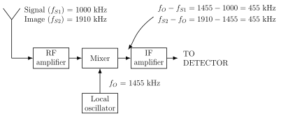
The IF is the difference between the oscillator frequency and the wanted signal : . But there is a second, undesired input , lying above the oscillator, that also produces the same IF because . This is the image frequency, given by — the wanted station plus twice the IF. If it is not removed before mixing, the image station is received at the same time as the wanted one and cannot afterwards be separated. A highly selective RF stage ahead of the mixer keeps the image out. For example, with a wanted carrier of 1000 kHz and the oscillator at 1455 kHz, a station at 1910 kHz (= 1455 + 455) also gives 455 kHz and is the image of the 1000 kHz station — the two are 2 x IF = 910 kHz apart.
The FM receiver
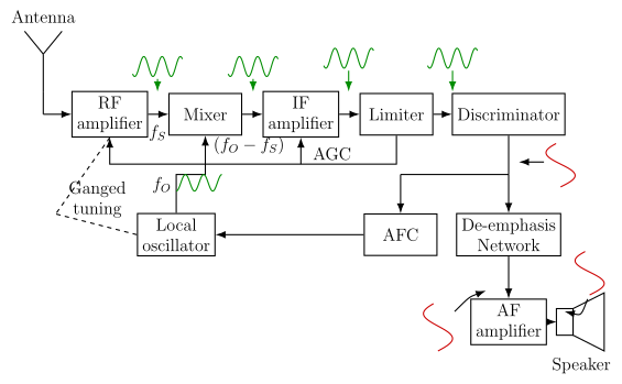
An FM receiver is also a superheterodyne, operating in the VHF band 88-108 MHz with an IF of 10.7 MHz. It keeps the RF-amplifier / mixer / local-oscillator / IF-amplifier chain of the AM set but adds a few FM-specific stages:
- RF amplifier — raises the signal level and must handle the wide 150 kHz bandwidth (2 x 75 kHz); it also rejects the image signal. …
Drawn by us to help you understand the concept clearly, and verified to make sure it's accurate. For exams, practice from your textbook's own diagram.
Textbook Figure 8.7.1 (Basic concept of superheterodyne receiver). A single Mixer block receives the incoming signal frequency from the left and the local-oscillator frequency from below, and outputs the difference , which is the intermediate frequency, to the IF ampl …
Drawn by us to help you understand the concept clearly, and verified to make sure it's accurate. For exams, practice from your textbook's own diagram.
Textbook Figure 8.7.2 (Block diagram of an AM superheterodyne). Signal chain, left to right: Antenna to RF amplifier () to Mixer, with a Local oscillator () feeding the mixer through ganged tuning; the mixer output goes to the IF amplifier, then the Diode detector, AF amplifier, Power amplifier and Speaker. An AGC line feeds back from the detector to …
Drawn by us to help you understand the concept clearly, and verified to make sure it's accurate. For exams, practice from your textbook's own diagram.
Textbook Figure 8.7.3 (Generation of second mixing product due to image frequency). The antenna feeds both the wanted signal kHz and its image kHz into the RF amplifier and mixer; with the local oscillator at kHz, both kHz and kHz, so both reach the IF amplifier. It il …
Drawn by us to help you understand the concept clearly, and verified to make sure it's accurate. For exams, practice from your textbook's own diagram.
Textbook Figure 8.7.4 (Block diagram of an FM superheterodyne receiver). Top chain: Antenna to RF amplifier () to Mixer to IF amplifier to Limiter to Discriminator, with a ganged Local oscillator () feeding the mixer and an AGC line to the earlier stages. From the discriminator the path runs through a De-emphasis network to the AF amplifier and Speaker, while an AFC block feeds a correction voltage back to the local oscillator. This ground …
For a superheterodyne receiver, for the wanted signal, and the image satisfies , giving . The image lies twice the IF above the wanted station and, once conver …
Textbook table (Choice of intermediate frequency).
| Type of receiver | Frequency range | Intermediate frequency |
|---|---|---|
| AM receiver | 438 kHz - 465 kHz | 455 kHz |
| FM receiver | 88 MHz - 108 MHz | 10.7 MHz |
| Television receiver (VHF band) | 54 MHz - 223 MHz | 36 MHz |
| A M receiver | F M receiver |
|---|---|
| Carrier frequencies are lower | Carrier frequencies are much higher |
| Bandwidth is smaller | Bandwidth is wider |
| Linear diode detector is used | Quadrature or PLL detector is used |
| Does not use limiter and de-emphasis circuits | Uses limiter and de-emphasis circuits |
| AGC is used | Both AGC and AFC are used |
| Fidelity is poor | Fidelity is good (better) |