Electronics · Ch 8 — Modulation and Demodulation
Introduction
Introduction
The purpose of any communication system is to carry information — a message signal — from a source to a distant receiver. Before that message can travel through a communication channel, it is processed by a key technique called modulation. Modulation is the process of superimposing the information contained in a low-frequency signal onto a high-frequency signal. Without it, practical electronic communication over any useful distance would not exist.
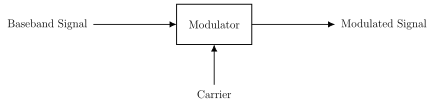
More formally, modulation is the process by which some characteristic of a high-frequency signal called the carrier is varied in step with the instantaneous value of another signal called the modulating signal. The low-frequency message is also called the intelligence signal or baseband signal. The higher-frequency carrier, being high enough in frequency to be radiated through free space as a radio wave, is termed a radio-frequency (RF) signal. The signal that comes out of the modulator is the modulated signal (Figure 8.1.1).
A sinusoidal carrier wave can be written in general as
There are three parameters associated with this carrier: its amplitude , its frequency and its phase . Depending on which one of these is varied in accordance with the amplitude of the modulating signal, the process is named:
- Amplitude modulation (AM) — the amplitude of the carrier is varied in proportion to the modulating signal, keeping frequency and phase constant.
- Frequency modulation (FM) — the frequency of the carrier is varied in proportion to the modulating signal, keeping amplitude and phase constant.
- Phase modulation (PM) — the phase of the carrier is varied in proportion to the modulating signal, keeping amplitude and frequency constant.
Frequency modulation and phase modulation both effectively vary the total angle of the carrier, so together they are called angle modulation.
Need for modulation
Modulation is used so that message signals can be transmitted effectively over long distances. The main reasons are:
- Length of antenna — For efficient radiation or reception, the minimum antenna length must be about one-fourth the wavelength of the signal, i.e. . A low audio frequency demands an impractically huge antenna. For example, a 20 kHz audio signal has m, needing an antenna of roughly 3750 m. If instead the audio is used to modulate a 10 MHz carrier, the required antenna length m — perfectly practical.
- Operating range — A higher-frequency wave carries greater energy, so it travels much farther. Low audio frequencies radiated directly cannot cover any useful distance. …
The process by which some characteristic (amplitude, frequency or phase) of a high-frequency carrier signal is varied in accordance with the instantaneous value of a lower-frequency modulating (message) signal, so that the information can …
, where is the carrier amplitude, the carrier frequency and the phase. Any one of these three param …
The low-frequency message is the baseband or intelligence signal; the high-frequency signal that carries it through free space as a radio wave is the carrier or radio-frequency (RF) signal. The modulat …
In amplitude modulation the carrier amplitude is varied with the message; in frequency modulation the carrier frequency is varied; in phase modulation the carrier phase is varied — in each case the other two …
Frequency modulation and phase modulation both vary the total instantaneous angle of the carrier, and so are grouped together under the single name angle modulation. In both, the carrier's frequency or phase — not its amplitude — is varied to carry the message, which is …
Minimum antenna length . A 20 kHz audio signal ( m) would need a ~3750 m antenna, but the same audio on a 10 MHz carrier needs only m — one of the key reas …
Drawn by us to help you understand the concept clearly, and verified to make sure it's accurate. For exams, practice from your textbook's own diagram.
Figure 8.1.1 (Basic block diagram of a modulator): a single block labelled 'Modulator' takes the baseband (message) signal in from the left and the carrier in from below, and delivers the modulated signal on the right. It captures the core idea of the chapter …