Electronics · Ch 5 — Operational Amplifiers
Introduction
Introduction
An operational amplifier (op-amp) is a direct-coupled, high-gain amplifier with high input impedance, low output impedance and high bandwidth, whose overall gain can be set precisely by external feedback. Because it can be configured to carry out mathematical operations such as addition, subtraction, inversion, differentiation and integration, it earns the name operational amplifier.
Internal block diagram. Internally an op-amp is built from four stages connected in a signal chain, as shown in Figure 5.1.1:
- Input stage — a differential amplifier. It provides high common-mode rejection ratio (CMRR), high input impedance and high voltage gain. This stage supplies the op-amp's two inputs: an inverting input and a non-inverting input.
- Gain stage — further increases the voltage gain. It is made of a Darlington pair (CC-CC configuration) followed by a CC-CE cascaded amplifier.
- DC level (shifting) stage — since the op-amp is basically a DC amplifier that uses no coupling capacitors, the quiescent (no-signal) DC voltage level shifts after every stage. An emitter follower is used here as a DC level shifter to bring the level back to its original value.
- Output stage — must present a low output impedance and be able to deliver a high output current. This is achieved with a complementary-symmetry push-pull amplifier circuit.
Two input lines and enter the input stage and a single amplified output leaves the output stage.
Circuit symbol and terminals. The op-amp is drawn as a triangle pointing towards the output (Figure 5.1.2). Every op-amp has the following five terminals:
- An inverting input (marked ), …
A direct-coupled, high-gain amplifier with high input impedance, low output impedance and high bandwidth, whose gain is controlled by external feedback. It can be configured to perform mathematical operations (addition, subtraction, inversion, differenti …

Drawn by us to help you understand the concept clearly, and verified to make sure it's accurate. For exams, practice from your textbook's own diagram.
Reproduces textbook Figure 5.1.1 (Block diagram of Op-Amp). Four rectangular blocks are connected left to right by arrows: Input Stage, Gain Stage, DC Level Stage and Output Stage. Two input lines and enter the input stage on the left; a single output leaves the output stage on the right. The figure matters because it shows how each internal stage contributes one property of the finished op-amp: differential i …
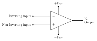
Drawn by us to help you understand the concept clearly, and verified to make sure it's accurate. For exams, practice from your textbook's own diagram.
Reproduces textbook Figure 5.1.2 (The circuit symbol of Op-Amp). A triangle points to the right; the two input terminals on the left are marked (inverting input) and (non-inverting input). Vertical terminals carry (top) and (bottom); the apex on the right is the output . This is the s …