Electronics · Ch 5 — Operational Amplifiers
Op-Amp as Differentiator and Integrator
Op-Amp as Differentiator and Integrator
This section covers two non-linear applications of the op-amp: the differentiator, whose output follows the derivative of the input, and the integrator, whose output follows the integral of the input.
Op-amp as a differentiator
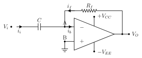
A differentiator gives an output proportional to the rate of change (derivative) of its input voltage. In figure 5.6.1 the input reaches the inverting terminal (node A) through a capacitor ; the non-inverting terminal is grounded and is the feedback resistor.
For the ideal op-amp and , so KCL at node A gives . Writing the capacitor's charging current as the rate of change of charge, , substituting , and putting :
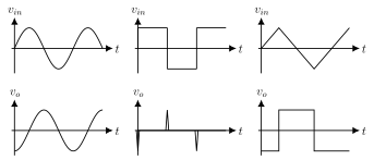
So the output is proportional to the derivative of the input. For proper working the time constant must satisfy , where is the period of the input waveform. Differentiators are used in wave-shaping circuits, as high-pass filters, and similar applications. Figure 5.6.2 shows the response: a sine input gives an inverted cosine output, a square input produces sharp spikes at its edges, and a triangular input yields a square wave.
Op-amp as an integrator
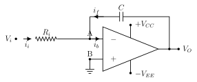
An integrator gives an output proportional to the integral of its input. In figure 5.6.3 the input reaches the inverting terminal through a resistor , the non-inverting terminal is grounded, and a capacitor forms the feedback element. …
Drawn by us to help you understand the concept clearly, and verified to make sure it's accurate. For exams, practice from your textbook's own diagram.
Figure 5.6.1 shows the op-amp differentiator. The input Vi reaches the inverting terminal (node A) through a series capacitor C (input current i_i); the feedback resistor Rf carries i_f from the output back to node A, and the non-inverting terminal (node B) is grounded. Supply pins +Vcc and -Vee, output Vo. The capacitor at the input and the resistor in feedb …
— the output is proportional to the derivative of the input. Proper functioning requires the time constant , where is th …
Drawn by us to help you understand the concept clearly, and verified to make sure it's accurate. For exams, practice from your textbook's own diagram.
Figure 5.6.2 shows three input-output waveform pairs for the differentiator. A sine input produces an inverted cosine output; a square input produces a train of alternating positive and negative spikes at its edges; a triangular input produces a square wave. Each pair is plotted as v_i …
Drawn by us to help you understand the concept clearly, and verified to make sure it's accurate. For exams, practice from your textbook's own diagram.
Figure 5.6.3 shows the op-amp integrator. The input Vi reaches the inverting terminal (node A) through a series resistor Ri (input current i_i); a feedback capacitor C carries i_f from the output back to node A, and the non-inverting terminal (node B) is grounded. Supply pins +Vcc and -Vee, output Vo. The resistor at the input and the capacitor …
— the output is proportional to the integral of the input. Proper functioning requires the time constant , where is …
Drawn by us to help you understand the concept clearly, and verified to make sure it's accurate. For exams, practice from your textbook's own diagram.
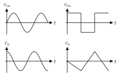
Figure 5.6.4 shows two input-output waveform pairs for the integrator. A sine input produces a cosine output; a square input produces a triangular wave. Each pair is plotted as v_in (top) against …