Electronics · Ch 5 — Operational Amplifiers
Logarithmic and Anti-logarithmic amplifiers
Logarithmic and Anti-logarithmic amplifiers
Logarithmic amplifier using op-amp
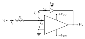
A logarithmic amplifier produces an output proportional to the natural logarithm of the input voltage. In figure 5.7.1 the input reaches the inverting terminal (node A) through a resistor , the non-inverting terminal is grounded, and a semiconductor diode is placed in the feedback path between node A and the output.
With the ideal op-amp and , KCL at node A gives , so . The voltage across the diode is . Using Shockley's diode equation (since ) and substituting :
Taking natural logarithms on both sides,
[!NOTE]
The official KTBS corrigendum corrects a sign in this derivation: the substituted diode-current step must read (a negative exponent, because ), not the shown in one printed line on this page. The corrected form is used above and is consistent with the final result.
Anti-logarithmic amplifier using op-amp
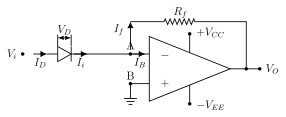
An anti-logarithmic amplifier produces an output proportional to the natural antilog (exponential) of the input voltage. In figure 5.7.2 the input reaches the inverting terminal through a semiconductor diode, the non-inverting terminal is grounded, and a resistor forms the feedback element — the diode and resistor swap roles compared with the log amplifier.
With and , KCL gives , and the feedback current is . The diode voltage is (since ). Using Shockley's equation :
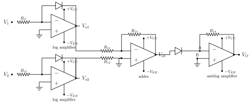
Application: multiplying two signals …
Drawn by us to help you understand the concept clearly, and verified to make sure it's accurate. For exams, practice from your textbook's own diagram.
Figure 5.7.1 shows the op-amp logarithmic amplifier. The input Vi reaches the inverting terminal (node A) through resistor Ri (current I_i); the non-inverting terminal is grounded. In the feedback path a semiconductor diode is connected between node A and the output, with its anode on the node-A side and cathode toward the output, so the diode current I_f = I_D flows from node A toward the output. The diode voltage V_D is marked across it. The diode' …
, so . Here is the diode reverse-saturation current, the diode ideality factor and the thermal voltage; derived from Shoc …
Drawn by us to help you understand the concept clearly, and verified to make sure it's accurate. For exams, practice from your textbook's own diagram.
Figure 5.7.2 shows the op-amp anti-logarithmic amplifier. The input Vi reaches the inverting terminal (node A) through a series semiconductor diode, with its anode on the input side and cathode toward node A, so the current I_D = I_i flows from Vi into node A; the diode voltage V_D is marked across it. The non-inverting terminal is grounded and a feedback resistor Rf connects the output back to node A. The diode …
with , so . Derived from Shockley's diode equation applied to the input diode. is the diode reverse-saturation current, the ideality factor, the thermal voltage and the feedback resistor; the input diode's exp …
Drawn by us to help you understand the concept clearly, and verified to make sure it's accurate. For exams, practice from your textbook's own diagram.
Figure 5.7.3 shows how log and anti-log amplifiers multiply two signals. V1 and V2 each pass through a log amplifier (diode in feedback) giving Vo1 and Vo2; an adder stage sums these to Vo3 = log_e(V1) + log_e(V2) = log_e(V1 x V2); a final anti-log amplifier (diode at input) produces an output Vo proportional to the product V1 x V2. …
, and after the anti-log stage — the output is proportional to the product of the two input signals. is the adder output summing the two logarithms; taking the antilog undoes the logarithm and recovers the prod …