Physics · Ch 13 — AC Circuits
AC Voltage Applied to a Capacitor
AC Voltage Applied to a Capacitor
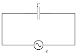
Now consider a circuit containing only a capacitor of capacitance C, connected to a source of alternating emf . At any instant, the charge q on the capacitor's plates is related to the instantaneous voltage across it by (since, for an ideal capacitor with no resistance anywhere in the loop, the instantaneous potential difference across the plates must always equal the source emf e). The instantaneous current flowing in the circuit is the rate of change of this charge: .
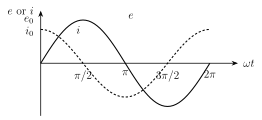
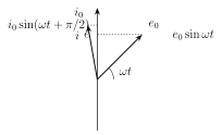
Writing this as , the peak current is . Comparing with , the current LEADS the emf by a phase angle of radian () -- the exact mirror image of the inductor's behaviour, where current instead LAGS. On the phasor diagram, the current phasor is drawn rotated ANTICLOCKWISE (ahead) of the emf phasor . …
Drawn by us to help you understand the concept clearly, and verified to make sure it's accurate. For exams, practice from your textbook's own diagram.
What this figure shows. A simple series circuit diagram showing a capacitor (two parallel-plate symbol, C) connected across an AC source, with the instantaneous emf e and instantaneous current i labelled on the connecting wires -- the purely capacitive analogue of Figs. 13.3 and 13.6, illustrating that as the source current reverses direction every half cycle, the capacitor plates are alternately charged and then discharged/recharged with opposite polarity, so a continuous alternating current flows in the external circuit even though no charge actu …
Drawn by us to help you understand the concept clearly, and verified to make sure it's accurate. For exams, practice from your textbook's own diagram.
What this figure shows. Two sinusoidal curves on the same axes (e and i vs , one full cycle), horizontally offset from each other by a quarter cycle in the OPPOSITE sense to the inductor case: the current curve i reaches ITS peak EARLIER than the emf curve e, at (or equivalently the i-curve is the e-curve shifted to the LEFT by ) -- so i crosses zero and reaches its peak a quarter-cycle BEFORE e does at each corresponding point, visually establishing the LEAD of current ahead of emf that is the defining electrical signature of a pure capacitor, the mirror …
Drawn by us to help you understand the concept clearly, and verified to make sure it's accurate. For exams, practice from your textbook's own diagram.
What this figure shows. A phasor diagram with fixed horizontal reference axis OX, showing the peak-emf phasor at angle anticlockwise from OX, and the peak-current phasor drawn turned a FURTHER ANTICLOCKWISE ahead of the phasor's direction (i.e. leading it), so the current phasor arrow sits ahead of the emf phasor arrow, both rotating together anticlockwise at the same rate while maintaining this fixed separation -- the mirror image of the inductor's phasor diagram (Fig. 13.8), wher …
Resistance | Reactance
Equally effective for AC and DC | Current is affected (reduced) but energy is not consumed (heat is not generated); the energy consumption by a real coil is due to its resistive component only
Its value is independent of the frequency of the AC | Inductive reactance () is directly proportional, and capacitive reactance () is inversely proportional, to the frequency of the AC …
Worked out. A capacitor of F is connected to an AC source of emf . Since current leads emf by in a pure capacitor, the instantaneous current has the form with peak A, giving A. An AC ammeter reads the rms value: A. This example demonstrates reading the peak current directly off (equivalently ) and then converting to the rms value that a real …