Physics · Ch 13 — AC Circuits
LCR Circuit (Series)
LCR Circuit (Series)
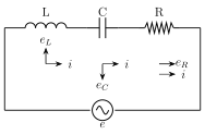
Now combine a resistor R, an ideal inductor L and an ideal capacitor C all in SERIES with a source of alternating emf, as in Fig. 13.12. Since they are in series, exactly the SAME current flows through all three elements at every instant, though each individually develops a voltage drop that is out of phase with this common current by a different amount, as established in the previous three sections: (in phase with i), (leading i by ), and (lagging i by ).
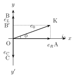
Because and point in exactly OPPOSITE directions on the phasor diagram (both perpendicular to the current phasor, but one rotated and the other ), only their DIFFERENCE, , survives as a net reactive voltage phasor, at right angles to . Adding the two remaining perpendicular phasors, (along the current direction) and (perpendicular to it), by the ordinary Pythagorean rule for perpendicular vectors gives the resultant applied voltage: .
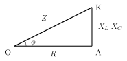
Comparing this with (an Ohm's-law-like relation) identifies the quantity as the IMPEDANCE of the series LCR circuit -- the total effective opposition offered jointly by the resistor, inductor and capacitor together to the flow of AC current, also measured in ohms, and equal to the ratio of rms voltage to rms current for the whole combination. (Its reciprocal is called the admittance, with SI unit siemens, or .) The phase angle by which the resultant voltage leads (or lags) the current follows from the same phasor triangle: , summarised compactly in the impedance triangle of Fig. 13.14, whose sides are R (base), (perpendicular) and Z (hypotenuse). The current in the LCR circuit is then while the applied emf is . …
Drawn by us to help you understand the concept clearly, and verified to make sure it's accurate. For exams, practice from your textbook's own diagram.
What this figure shows. A single-loop series circuit diagram showing a resistor R, an inductor L and a capacitor C connected one after another in SERIES (so the same instantaneous current i flows through all three), the whole series combination connected across an AC source, with the instantaneous emf e of the source and the common current i both labelled -- the combined circuit whose separate R-only, L-only and C-only behaviours (Figs. 13.3, 13.6, 13.9) are now superposed using phasor addition, since the three elements' individual voltage drops are not in pha …
Drawn by us to help you understand the concept clearly, and verified to make sure it's accurate. For exams, practice from your textbook's own diagram.
What this figure shows. A phasor diagram built by vector (phasor) addition: the current phasor drawn along the positive X-axis as the common reference (since current is the same through R, L and C in series); the resistor's voltage phasor drawn ALONG the same direction as (in phase, along OA on the X-axis); the inductor's voltage phasor drawn perpendicular to , rotated ANTICLOCKWISE from it (leading); the capacitor's voltage phasor drawn perpendicular to but rotated CLOCKWISE (lagging), i.e. exactly opposite to along OY'. Since and are apart, only their DIFFERENCE survives as the net reactive voltage OB', and the diagonal OK of the rectangle formed by OA (along ) and OB' (the net reactive voltage) gives …
Drawn by us to help you understand the concept clearly, and verified to make sure it's accurate. For exams, practice from your textbook's own diagram.
What this figure shows. A right-angled triangle (derived directly from dividing every side of the voltage phasor triangle in Fig. 13.13 by the common current ): the base of the triangle represents the pure Ohmic resistance R (horizontal), the vertical side (perpendicular to the base) represents the net reactance , and the hypotenuse (the diagonal connecting them) represents the impedance . The angle between the base (R) and the hypotenuse (Z) is marked as , the same phase angle by which the voltage leads (or lags) the current, satisfying -- giving a purely geometric (right-triangle) way to remember and …
Worked out. A 100 mH inductor, a 25 capacitor and a 15 resistor are connected in series to a 120 V (rms), 50 Hz AC source. At RESONANCE (the frequency at which , developed fully in section 13.8), the reactive part of the impedance cancels exactly, leaving the circuit purely resistive: . The current at resonance is then simply A. The resonant frequency itself is found from Hz -- notably this resonant frequency does NOT depend on the resistance R or on the actual 50 Hz supply frequency at all, only on L and C, and is worked out here purely to characteri …
Worked out. A coil of inductance H and resistance is connected to a 200 V, 50 Hz AC supply (no capacitor, so this is a series RL circuit, i.e. the C-terms of the general LCR formulas simply drop out). The inductive reactance is , giving impedance . The phase angle follows from , so rad. Since this phase angle corresponds to a fraction of one full cycle ( rad s), the actual TIME LAG between the peaks of voltage and current is s -- this example's key device is converting a phase angle …