Physics · Ch 13 — AC Circuits
AC Voltage Applied to a Resistor
AC Voltage Applied to a Resistor
Consider a resistor of resistance R connected directly across an AC source of instantaneous emf . Since the potential drop across the resistance must, at every instant, equal the applied emf (, from Ohm's law applied instantaneously), substituting the given emf gives , so , where the peak current is .
Comparing this result with shows that the current i and the emf e are described by the EXACT SAME sine function of -- both are proportional to , with no phase shift between them at all. This means current and voltage reach zero, their positive maximum, and their negative minimum SIMULTANEOUSLY at every instant throughout the cycle: they are exactly IN PHASE. Comparing with the familiar (DC) Ohm's law form directly shows that a resistor's behaviour is IDENTICAL for AC and for DC -- there is no frequency-dependence at all, and R reduces AC and DC current equally effectively. This is the …
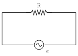
Drawn by us to help you understand the concept clearly, and verified to make sure it's accurate. For exams, practice from your textbook's own diagram.
What this figure shows. A simple series circuit diagram showing a resistor of resistance R connected across the two terminals of an AC source (drawn as a circle with a sine-wave symbol inside, or the standard AC-source circle-with-tilde symbol), with a single loop of connecting wire joining them, and the instantaneous emf e and instantaneous current i both labelled on the connecting wires -- the simplest possible AC circuit, containing only R and nothing else (no L, no C), used to derive the purely-resis …
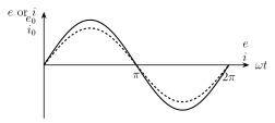
Drawn by us to help you understand the concept clearly, and verified to make sure it's accurate. For exams, practice from your textbook's own diagram.
What this figure shows. Two sinusoidal curves plotted on the SAME set of axes (e and i both on the vertical axis, on the horizontal axis, spanning one full cycle from 0 to ): one curve for the instantaneous emf e (peak ) and one for the instantaneous current i (peak ), drawn as two sine waves of possibly different amplitude but starting together at the origin, rising together, peaking together at , crossing zero together at , reaching their minima together at , and returning to zero together at -- visually demonstrating that e and i reach zero, their maximum, and their minimum values SIMULTANEOUSLY at every point in the cycle, i.e. there is no horizontal (pha …
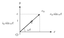
Drawn by us to help you understand the concept clearly, and verified to make sure it's accurate. For exams, practice from your textbook's own diagram.
What this figure shows. A phasor diagram with a fixed horizontal reference axis OX, showing TWO phasor arrows drawn EXACTLY along the same line/direction from the origin O, both making the same angle with OX: one arrow representing the peak emf and the other representing the peak current , drawn overlapping or immediately alongside each other (never separated by any angle) to emphasise that the phase angle between the current and voltage phasors through a pure resistor is exactly zero -- unlike the inductor and capacitor cases that follow, where the two phasors will be …
Worked out. An alternating voltage is connected across a pure resistor of . Comparing with gives rad/s and V. The frequency follows from : Hz. The rms voltage is V, and since a resistor is purely Ohmic for both AC and DC, the rms current follows directly from Ohm's law applied to rms values: A. This example demonstrates that rms voltage and rms current obey the ordinary Ohm's law relation for a resistor, exactly as …