Physics · Ch 13 — AC Circuits
AC Voltage Applied to an Inductor
AC Voltage Applied to an Inductor
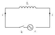
Now consider a circuit containing only a pure inductor of inductance L (its own resistance assumed negligible), connected to a source of alternating emf . As current begins to flow and grow, the changing magnetic flux linked with the coil induces a back-emf that, by Lenz's law, opposes the applied emf: . Since there is no resistance anywhere in this purely inductive circuit, the applied emf must at every instant be exactly equal and opposite to this induced emf for current to keep flowing (Kirchhoff's voltage law), giving .
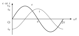
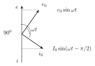
Integrating this equation with respect to time, and noting that the constant of integration must be zero (since the emf oscillates symmetrically about zero, the current it drives must also oscillate about zero, with no steady/time-independent component), gives , where the peak current is . Comparing this with shows that the current LAGS the emf by a phase angle of radian () -- equivalently, the voltage across L is said to LEAD the current by . On the phasor diagram, this means the current phasor is drawn rotated CLOCKWISE from the emf phasor . …
Drawn by us to help you understand the concept clearly, and verified to make sure it's accurate. For exams, practice from your textbook's own diagram.
What this figure shows. A simple series circuit diagram showing a pure inductor (coil symbol, L) connected across an AC source, with a switch/key k in the loop, and the instantaneous emf e and instantaneous current i labelled -- the purely inductive analogue of Fig. 13.3, with the inductor assumed to have negligible ohmic resistance so that the only opposition to current comes from the self-induced back-emf (Lenz's law) that opposes the applied emf as the key is closed …
Drawn by us to help you understand the concept clearly, and verified to make sure it's accurate. For exams, practice from your textbook's own diagram.
What this figure shows. Two sinusoidal curves on the same axes (e and i vs , one full cycle), both of the same general sine shape but HORIZONTALLY OFFSET from each other by a quarter cycle ( radian): the e curve peaks at as usual, while the i curve (current) reaches ITS peak later, at (i.e. i is delayed/lags behind e by ) -- so wherever e crosses zero going upward, i is still at its most negative, and i only reaches zero a quarter-cycle after e does. The curves visually establish the lag of current behind emf that is the defining elec …
Drawn by us to help you understand the concept clearly, and verified to make sure it's accurate. For exams, practice from your textbook's own diagram.
What this figure shows. A phasor diagram with fixed horizontal reference axis OX, showing the peak-emf phasor drawn at angle anticlockwise from OX (as in the general phasor convention), and the peak-current phasor drawn turned CLOCKWISE by from the phasor's direction (i.e. lagging behind it), so the angle between the two phasor arrows is exactly with trailing -- visually encoding 'current lags voltage by in a pure inductor', the mirror image of the capacitor's phasor diagram (Fig. 13.11) wher …
Worked out. An inductor of inductance mH H is connected to an AC source of peak emf V and frequency Hz. The peak current is found via A. For the second part, since current LAGS emf by in a pure inductor, the instant at which current reaches its own peak value is exactly the instant at which the emf phasor has already rotated a further past where it was when current started rising from zero -- concretely, at the moment , the emf phasor is at the position where , so the instantaneous voltage of the source at that moment is zero. This example fixes the practical consequence of the lag: peak current and peak voltage NEVER occur at the same …