Physics · Ch 12 — Electromagnetic Induction
Generators
Generators
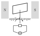
An electric generator's basic construction mirrors that of the electric motor studied earlier: an armature (a coil) is mounted so it can rotate within a magnetic field, but where a motor is driven electrically to produce mechanical rotation, a generator is driven by an EXTERNAL mechanical torque to produce electricity. As the armature's conductor wires cut across the magnetic field lines, a motional emf () is induced across the terminals brought out through the commutator/slip rings, and this emf is proportional to the armature's angular speed .
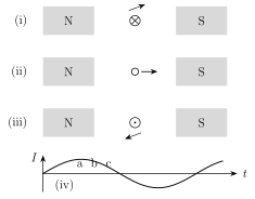
Tracking a single conductor of the armature through one full rotation shows why the output is inherently alternating: in position (i), the conductor moves directly across the field lines, giving maximum induced emf; in position (ii), a quarter-turn later, it moves PARALLEL to the field, giving zero emf; in position (iii), a further quarter-turn on, it again cuts across the lines but now moving in the opposite sense, giving an emf equal in magnitude but OPPOSITE in direction to position (i). Plotting the current through an external lamp against time therefore traces out a sinusoidal wave.
This can be made quantitative: for a coil of N turns rotating at constant angular velocity , if is the (time-varying) angle between the field and the coil's area vector (taking at t=0), the flux linked with the coil at any instant is . Applying Faraday's law, the induced emf is , where is the peak (amplitude) emf and f is the frequency of rotation of the coil.
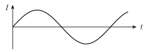
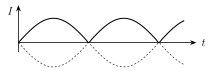
Since oscillates between +1 and -1, the polarity of e reverses periodically -- this periodically-reversing output is called alternating current (AC), with its extreme values occurring at and (where the flux is changing fastest). India's domestic AC supply alternates at 50 cycles per second (50 Hz). For applications needing a STEADY (one-directional) current, a commutator can be used instead of slip rings: it acts as a rapid mechanical reversing switch that flips the connection to the armature exactly in step with the current's own natural reversals, converting the sinusoidal AC into a one-directional but still time-varying 'pulsating DC' waveform. Modern AC motors/generators, being commutator-free, are generally more compact and rugged than their DC counterparts. …
Drawn by us to help you understand the concept clearly, and verified to make sure it's accurate. For exams, practice from your textbook's own diagram.
What this figure shows. Shows the basic schematic layout of a simple electric generator: an armature (a coil or a set of conductor loops) mounted on a shaft so it can be mechanically turned by an outside torque, positioned between the poles of a magnet (or field coils) so it rotates within their magnetic field, with its two ends brought out through a commutator/slip-ring-and-brush arrangement to external terminals feeding a load (such as a lamp). The figure establishes that a generator's construction is essentially the same hardware as a motor's, but driven mechanically (turned …
Drawn by us to help you understand the concept clearly, and verified to make sure it's accurate. For exams, practice from your textbook's own diagram.
What this figure shows. Shows one conductor of the rotating armature depicted at four successive positions (i), (ii), (iii) and a graph (iv) as it completes one rotation. At position (i) the conductor moves directly upward, cutting straight across the field lines and inducing maximum emf; at position (ii), a quarter turn on, it moves parallel to the field, inducing zero emf; at position (iii), a further quarter turn on, it moves downward across the field lines, inducing an emf equal in size to (i) but opposite in direction; part (iv) is a graph of the resulting current through an external lamp plotted against time, drawn as a smooth sine wave that peaks at position (i)'s instant, cros …
Drawn by us to help you understand the concept clearly, and verified to make sure it's accurate. For exams, practice from your textbook's own diagram.
What this figure shows. A graph of the generator's output current (or emf) against time, drawn as a smooth, symmetric sine wave that swings between equal positive and negative peak values and periodically reverses sign -- the current direction through the external circuit literally reverses every half-cycle. The figure visually defines alternating current (AC): current whose direction changes periodically, with the number of positive-to-negative-and-back reversals per second defining its frequency (5 …
Drawn by us to help you understand the concept clearly, and verified to make sure it's accurate. For exams, practice from your textbook's own diagram.
What this figure shows. A graph of the output current against time for a generator fitted with a commutator (a rapid mechanical reversing switch) instead of plain slip rings: rather than swinging symmetrically between positive and negative like Fig. 12.8(c), the curve is drawn as a series of humps that all stay on the SAME (positive) side of the time axis, dipping down to (but not below) zero between humps, since the commutator flips the external connections at exactly the moments the internal current would otherwise reverse. The figure defines pulsating DC: a current that is always one-directional but still varies in magnitude …
Worked out. A rectangular armature loop DABC of conducting wire is rotated at 1500 rpm within a uniform magnetic field of B=0.5 T, with connections brought out through sliding contacts to terminals P and Q; side AB has length l=10 cm and sweeps out a circle of radius r=4 cm as the armature turns. The tangential speed of side AB is m/s, so -- since AB is at the instant shown cutting the field lines perpendicularly (the maximum-emf orientation, ) -- the induced emf across it (and hence between P and Q, since the other two sides BC and DA and the stationary lead wires contribute zero emf) is mV, matching the exa …