Physics · Ch 12 — Electromagnetic Induction
Self-Inductance
Self-Inductance
Consider an isolated circuit (coil) carrying a current that is CHANGING with time. The changing current itself continuously alters the magnetic flux that this same current sets up and links through its own circuit -- and by Faraday's law, this self-produced changing flux must itself induce an emf back in the very same circuit. This phenomenon -- a circuit inducing an emf in itself purely because ITS OWN current is changing -- is called self-inductance.
If is the flux linked with the circuit (due to its own current i) at some instant, then since (and hence ) is always directly proportional to the current producing it, , i.e. , where the constant of proportionality L is called the self-inductance (or coefficient of self-induction) of the circuit; L depends only on the geometry of the circuit and any magnetic material present, never on the current itself. For a closely-wound coil of N turns (where the same flux links every turn), the total flux LINKAGE is .
Differentiating with respect to time (with L constant) and using Faraday's law gives the induced (self-induced) emf directly in terms of L: . This is often taken as the DEFINING relation for L: the self-inductance of a circuit is the induced emf produced per unit rate of change of current in it, so that (or, from the flux definition, -- the flux linked per unit current). Comparing units: since is in volts and is in amperes per second, L is measured in volt-seconds-per-ampere, a unit given the name henry (H); 1 henry = 1 ohm-second -- corresponding to an induced emf of 1 V for a rate of change of current of 1 A/s.
For a long solenoid of N turns, length l, cross-sectional area A and n = N/l turns per unit length, the interior field is , so the flux linkage over the interior (of volume Al) is , giving inductance , i.e. inductance PER UNIT LENGTH near the middle of a long solenoid is (d the solenoid's diameter). Since L must have the dimensions of (as n is a number per unit length), this also shows that itself can be expressed in henry/metre (H/m).
For inductors combined in a circuit, series and parallel combination rules mirror those for resistors: in series, and in parallel -- so a parallel combination's inductance is always LESS than that of the smallest individual inductor, exactly analogous to resistors in parallel. …
Drawn by us to help you understand the concept clearly, and verified to make sure it's accurate. For exams, practice from your textbook's own diagram.
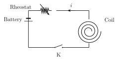
What this figure shows. Shows a single coil of wire, drawn schematically (e.g. as a helix or a set of loops), carrying a current i whose value is indicated as changing with time (e.g. by a time-varying current label or a small graph of i against t alongside the coil), together with the magnetic field lines the coil's own current produces threading back through the coil's own turns. The figure establishes the basic self-inductance scenario: a single isolated circuit whose own changing current changes the very flux linked with itself, which is the sou …
Worked out. Derives, then numerically evaluates, the self-inductance of a toroid of major (loop) radius R and circular cross-section of radius r, with N turns, in the thin-toroid limit r << R where the interior field can be approximated as uniform across the cross-section, . The flux linking each turn is then , giving self-inductance . For the given values N=1200 turns, r=2.0 cm, R=15 cm, this evaluates to H (about 2.41 mH), matching the example …
Worked out. A uniformly-wound air-core solenoid has N=200 turns, length l=20 cm and cross-sectional area A=5 . Using , the self-inductance evaluates to mH. The example then asks for the induced emf if the current through the solenoid is decreasing at a rate of 60 A/s, giving mV, matching the example's own printed results for both pa …
Worked out. A closely-wound coil of N=200 turns has self-inductance L=10 mH and carries a current i=4 mA. Using Wb for the total flux linked with the coil, the flux THROUGH THE CROSS-SECTION of the coil (i.e. the flux per single turn) is this total divided by N: Wb, matching the example's own printed result. …