Physics · Ch 12 — Electromagnetic Induction
Mutual Inductance (M)
Mutual Inductance (M)
Now consider two separate coils placed near each other, coil 1 and coil 2. A steady current flowing in coil 1 sets up a magnetic field throughout the surrounding region, including at coil 2; the resulting flux linked with coil 2's own area is . Since (and hence ) is proportional to as long as the coils' relative position is fixed, , where the proportionality constant is the mutual inductance of coil 2 WITH RESPECT TO coil 1. If varies (slowly enough that the quasi-static field relation still holds), varies in step, inducing an emf in coil 2: .
By an identical argument with the roles reversed -- a current in coil 2 producing flux through coil 1, and hence an emf in coil 1 -- a remarkable symmetry emerges: , regardless of the two coils' shapes, sizes or relative geometry. This lets M be defined equally validly as the flux linked with one circuit per unit current in the OTHER: , or (more commonly, calling the current-carrying coil the PRIMARY and the other the SECONDARY) as the flux linked with the secondary per unit current in the primary, giving the standard relation . The unit of M, like L, is the henry: a mutual inductance of 1 H means a current changing at 1 A/s in the primary induces exactly 1 V in the secondary. (An equivalent, less commonly used, definition treats M as the mutual potential energy of the two circuits per unit current flowing in each.)
The extent of coupling between the two coils is captured by the coefficient of coupling K (always ), related to M and the two self-inductances by . K depends on the fraction of coil 1's flux that actually reaches coil 2: coils wound on a common iron core couple almost perfectly (); air-core coils in typical use are tightly coupled if K > 0.5 and loosely coupled if K < 0.5 (K for radio-frequency coils, for instance, is typically only 0.001-0.05); and coupling is minimised (K small) by orienting the coils' axes at right angles and placing them as far apart as possible -- a trick deliberately used in appliances such as clothes dryers, where the heating coils are counter-wound specifically to cancel their combined field and keep any induced emf on the metal casing safely low, since (unlike in a transformer, where a LARGE M is exactly what's wanted) a large stray M is a hazard there. …
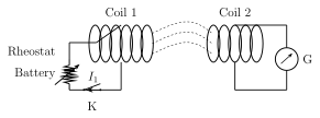
Drawn by us to help you understand the concept clearly, and verified to make sure it's accurate. For exams, practice from your textbook's own diagram.
What this figure shows. Shows two separate coils, coil 1 and coil 2, positioned near each other (e.g. coaxially, one behind the other, or side by side), with coil 1 carrying a current from an external source and coil 2 connected only to a galvanometer or left open. Field lines from coil 1's current are drawn spreading outward, with a portion of them shown passing through (linking) coil 2's own turns, representing the flux . The figure establishes the two-coil geometry that defines mutual inductance: how much of one …
Worked out. Models a wireless charger's base unit as a solenoid (coil B) of length l, turns and cross-sectional area A carrying current , with the handle's coil (coil H, turns) fitting coaxially and completely around the base solenoid when docked. The base solenoid's interior field is , so the flux through each turn of the surrounding handle coil is , giving flux linkage and hence mutual inductance -- the general (symbolic) result this worked example derives, with no numeric values …
Worked out. Two coils with self-inductances =75 mH and =55 mH are coupled with coefficient of coupling K=0.75. Using , the mutual inductance evaluates to mH, matching the example's own printed result. …
Worked out. Two coils have self-inductances =5 H and =4 H, and mutual inductance M=1.5 H. Using , the coefficient of coupling evaluates to , i.e. about 33.5%, matching the example's own printed result. …