Physics · Ch 12 — Electromagnetic Induction
Induction and Energy Transfer
Induction and Energy Transfer
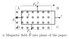
Consider a rectangular conducting loop ABCD being pulled with constant velocity out of a region of uniform magnetic field (the dashed lines in the standard figure mark the field's boundary). As the loop is withdrawn, the AREA of the loop still lying within the field shrinks, so the flux linked with the loop, (L the loop's width, x the still-immersed length), decreases with time. By Faraday's law the resulting induced emf has magnitude , driving an induced current of magnitude around the loop's total resistance R, in a direction fixed by the right-hand rule.
The three loop segments still within the field each experience a force ; by the loop's symmetry, the forces on the two segments parallel to the direction of motion cancel exactly, leaving a single net force directed OPPOSITE to the external pulling force F needed to keep the loop moving at constant velocity -- so . …
Drawn by us to help you understand the concept clearly, and verified to make sure it's accurate. For exams, practice from your textbook's own diagram.
What this figure shows. Shows a rectangular conducting loop ABCD, of width L, being pulled to the right with a constant velocity out of a region of uniform magnetic field (the field region's boundary is marked with dashed lines, so the loop is shown straddling the boundary, partly inside and partly outside the field). Force arrows , and are drawn on the three loop segments still within the field, representing the magnetic forces the induced current in those segments experiences; an external applied force is drawn on the loop (opposite in direction to the net magnetic force) representing what must be supplied to …
Drawn by us to help you understand the concept clearly, and verified to make sure it's accurate. For exams, practice from your textbook's own diagram.
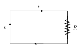
What this figure shows. An equivalent-circuit-style diagram representing the same moving loop of Fig. 12.9(a) abstracted into its electrical elements: an emf source e (representing the motional emf induced as the loop's enclosed area shrinks) drawn on one side, connected to the loop's total (collective) resistance R drawn on the other side, with the induced current i flowing around this simple series circuit, its direction fixed by the right-hand rule. The figure translates the physical picture of Fig. 12.9(a) into the simple e-R circuit used to derive the power balance between mechanical work done pulling the loop and heat dissipated …