Physics · Ch 12 — Electromagnetic Induction
Transformer
Transformer
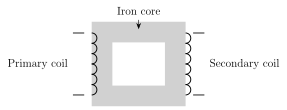
Mutual inductance is the operating principle behind every kind of transformer -- a device that changes an alternating voltage from one value to another (step-up or step-down), commonly seen mounted on roadside poles supplying local power distribution. A transformer consists of two electrically-insulated coils, the primary (input) and secondary (output), both wound on a common soft-iron core, which channels almost all of the primary's flux through the secondary as well (i.e. couples them as tightly as practically possible, ).
When an alternating voltage is applied to the primary, the resulting sinusoidally-varying primary current produces a correspondingly sinusoidal flux in the shared iron core; since this same changing flux links BOTH coils, an emf is induced in each. If is the flux linked per turn common to both coils at instant t, and , are the numbers of turns in the primary and secondary respectively, the flux linked with each coil is and , so the induced emfs are and ; dividing, -- the transformer equation. The ratio is called the turns ratio (or transformer ratio).
For an IDEAL transformer (no losses), input power exactly equals output power: , i.e. . Combining this with the transformer equation gives -- voltage and current transform in EXACTLY inverse ratio to each other, so power is conserved. Two cases follow directly: if , then (a step-up transformer) but -- the secondary delivers a higher voltage at correspondingly LOWER current; if , then (step-down) but -- the secondary delivers a lower voltage at correspondingly higher current. …
Drawn by us to help you understand the concept clearly, and verified to make sure it's accurate. For exams, practice from your textbook's own diagram.
What this figure shows. Shows a closed rectangular (or similar) soft-iron core, with two separate coils of wire wound around different limbs (or the same limb, layered) of this core: the primary coil, connected to an external AC voltage source, and the secondary coil, connected to an external load, with the two coils electrically insulated from each other but magnetically linked through the shared iron core. The core is drawn as a continuous closed loop of iron so that essentially all the magnetic flux produced by the primary's current is channelled through the secondary as well, establishing the near-total (tight) magnetic coupling a real transfor …