Physics · Ch 8 — Electrostatics
Capacitors in Parallel
Capacitors in Parallel
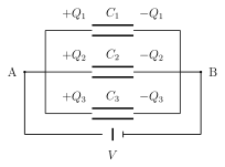
Capacitors are said to be connected in PARALLEL when all of their first plates are joined together to one single common terminal A (connected onward to the applied source), and all of their second plates are joined together to a second common terminal B (typically earthed). Every capacitor in such a bank therefore experiences the SAME potential difference V across it -- but, unlike the series case, there is no requirement at all that they carry the same charge; each is free to hold whatever charge its own individual capacitance dictates at that shared voltage.
If a total charge Q is supplied at terminal A, it distributes itself among the parallel capacitors in direct proportion to each one's own capacitance: (using for each, since all share the same V). Defining the equivalent parallel capacitance as and substituting gives ; the common factor V cancels from every term, leaving simply for three capacitors in parallel -- generalising directly to for capacitors in parallel: the equivalent parallel capacitance is nothing more than the plain SUM of the individual capacitances. Unlike the series case, adding another capacitor to a parallel bank can only ever GROW the overall equivalent capacitance, making always LARGER than even the single largest capacitance already present in the group. If all capacitors happen to be identical, each of value , this simplifies to . …
Drawn by us to help you understand the concept clearly, and verified to make sure it's accurate. For exams, practice from your textbook's own diagram.
What this figure shows. Three capacitors drawn side by side, all with their first (left) plates wired together to one common node/terminal A, which connects onward to the applied source, and all their second (right) plates wired together to a second common node B, which is connected to earth -- the standard parallel-bank circuit diagram from which the shared-voltage property and the charge-splitting relation $Q=Q_1+Q_2+Q_3=(C_1+C_2+C_3) …
Worked out. States the standing practical rule for when to reach for a parallel combination rather than a series one: capacitors are combined in parallel specifically when a LARGE overall capacitance is required while the potential difference across each individual capacitor is to be kept small -- the reverse situation to the series case, where a high voltage needs dividing safely across several smaller-rated capacitors. Since always grows with every additional capacitor added to the bank (never shrinking below any single one, unlike series), stacking more capacitors in parallel is the direct, reliable way to build up a larger total capa …