Physics · Ch 2 — Mechanical Properties of Fluids
Bernoulli's Equation
Bernoulli's Equation
Observing a river, one notices that the speed of the water decreases in a wider stretch of the river and increases in a narrower stretch. From this observation, one might guess that the pressure within the river's water is greater in the narrower stretches — but this guess is exactly backwards: the pressure within the fluid is actually lower in the narrower part of the river and higher in the wider part. This was discovered experimentally by the Swiss scientist Daniel Bernoulli (1700-1782), working with fluid flowing inside pipes: he observed that the speed of a fluid increases in a narrow region of a pipe, while the internal pressure of the fluid in that same narrow region simultaneously decreases. This phenomenon is called Bernoulli's principle.
Bernoulli's equation relates the speed of a fluid at a point, the pressure at that point, and the height of that point above some chosen reference level; it is, at its core, an application of the work-energy theorem to a fluid in flow. Because Bernoulli's principle is fully consistent with the general principle of conservation of energy, it can be derived directly from energy conservation.
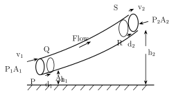
Consider the flow of an ideal fluid through a tube of varying cross-section and height, and focus on an element of fluid lying between an entry cross-section P and an exit cross-section R. Let and be the fluid's speed at the lower end P and the upper end R respectively; and the cross-sectional area at P and R; and the pressure of the fluid at P and R; and , the distances travelled at P and R respectively, over a small time interval dt, by fluid moving at and . The forces and act on the fluid at areas (at P) and (at R) respectively. Because the fluid is incompressible, the volume dV of fluid passing through any cross-section during time dt is the same everywhere along the tube:
Since the fluid is ideal, there is no internal friction at all within it (and even for a real fluid like water, the energy lost to viscous friction is negligible in practice) — so the only non-gravitational force doing work on this fluid element as it moves from P to R is the pressure exerted by the surrounding fluid. The net work W done on the element by this surrounding pressure, over the move from P to R, is:
(the second term carries a negative sign because the pressure force at R opposes the displacement of the fluid). Using Eq. (2.41), this becomes:
Because this work W arises purely from forces other than the conservative force of gravity, it must equal the resulting change in the fluid element's total mechanical energy — its kinetic energy plus its gravitational potential energy:
At the start of the time interval dt, the mass and kinetic energy of the fluid element between P and the neighbouring section Q are and respectively; at the end of dt, the kinetic energy of the fluid now between the corresponding sections R and S is . So the net change in kinetic energy during dt is:
(using from Eq. 2.41). Similarly, at the start of dt, the gravitational potential energy of the mass m of fluid between P and Q is , and at the end of dt, the potential energy of the same mass, now between R and S, is ; so the net change in potential energy during dt is:
Substituting Eqs. (2.42), (2.44) and (2.45) into Eq. (2.43):
Dividing throughout by dV:
This is Bernoulli's equation: it states that the work done per unit volume of a fluid, by the surrounding fluid, equals the sum of the changes in kinetic and potential energy per unit volume that occur during the flow. Equation (2.46) can equally be rewritten, collecting P, Q terms on each side, as:
Dimensionally, pressure is an energy per unit volume, and both terms on the right-hand side of Eq. (2.46) also have the dimensions of energy per unit volume — so the left-hand side, P, is often referred to as the pressure energy per unit volume, or pressure head; the term is called the velocity head, and the potential head. In other words, Bernoulli's principle is simply the principle of conservation of energy, applied directly to a flowing fluid.
Applications of Bernoulli's equation:
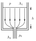
a) Speed of efflux (Torricelli's theorem). The word 'efflux' means fluid outflow. Torricelli discovered that the speed of efflux from an open tank is given by a formula identical to that of a freely falling body. Consider a liquid of density ρ filled in a tank of large cross-sectional area , with an orifice of cross-sectional area at the bottom, where . Let and be the speeds of the liquid at and respectively. Since both the inlet (free surface) and the outlet (orifice) are exposed to the atmosphere, the pressure at both equals atmospheric pressure . If h is the height of the free surface above the orifice, Bernoulli's equation gives:
Using the continuity equation, , and substituting into Eq. (2.49):
and if , this reduces to:
This is the speed of a liquid flowing out through an orifice at depth h below its free surface — identical to the speed a particle would reach falling freely under gravity through the same height h.
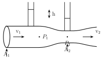
b) Venturi tube. A Venturi tube is used to measure the speed of flow of a fluid inside a pipe; it has a constriction built into the tube, and as fluid passes through this constriction its speed increases (per the equation of continuity), so its pressure correspondingly decreases (per Bernoulli's equation). If a fluid of density ρ flows through a Venturi tube with cross-sectional area (speed , pressure ) at the wide part and (speed , pressure ) at the constriction, Bernoulli's equation (with the tube horizontal, so height terms drop out) gives:
Two vertical tubes connected to the Venturi tube at and show a visible difference h in liquid-column height, related to the pressure difference by ; substituting into Eq. (2.51):
Using the continuity equation, , to substitute in terms of (or vice versa) in Eq. (2.52), the fluid's actual rate of flow can be calculated purely from the two known areas and and the measured level difference h. …
Drawn by us to help you understand the concept clearly, and verified to make sure it's accurate. For exams, practice from your textbook's own diagram.
What this figure shows. A flow tube of arbitrarily varying cross-sectional area and height is shown, with a fluid element marked between a lower entry cross-section P (area , speed , pressure , height ) and a higher exit cross-section R (area , speed , pressure , height ); the element is shown travelling distances and respectively at P and R during a small time interval dt, with the forces and marked acting on the fluid at each end. This is the exact setup used to derive Bernoulli's equation via the work-energy theorem, using the fact that (the volume of fluid passing any cross-section in time dt) to simplify the net …
Drawn by us to help you understand the concept clearly, and verified to make sure it's accurate. For exams, practice from your textbook's own diagram.
What this figure shows. A tank of large cross-sectional area , filled with liquid of density ρ, is shown with a small orifice of cross-sectional area () located at its bottom, and liquid flowing out through the orifice under the pressure of the liquid column above it. Both the tank's open top and the orifice are exposed to the atmosphere, so both are at atmospheric pressure ; the height of the free surface above the orifice is marked as h. This is the setup Torricelli used to derive the speed of efflux — applying Bernoulli's equation between the free surface and the orifice, combined with the continuity equation to eliminate (since makes negligible), gives , ex …
Drawn by us to help you understand the concept clearly, and verified to make sure it's accurate. For exams, practice from your textbook's own diagram.
What this figure shows. A horizontal tube is shown with a wider section of cross-sectional area (speed , pressure ) narrowing smoothly into a constricted section of cross-sectional area (speed , pressure ), with two open vertical tubes (a simple manometer arrangement) connected upward from the wide section and the narrow constriction respectively; a visible difference in liquid column height h is shown between the two vertical tubes. By the continuity equation the fluid speeds up as it passes through the narrower constriction, and by Bernoulli's equation its pressure correspondingly drops there — directly displayed by the lower liquid level in the vertical tube conne …
Drawn by us to help you understand the concept clearly, and verified to make sure it's accurate. For exams, practice from your textbook's own diagram.
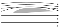
What this figure shows. The characteristic curved, asymmetric cross-sectional shape of an aeroplane wing (an aerofoil) is shown, with several streamlines drawn flowing over both its upper (more strongly curved) surface and its lower (comparatively flatter) surface; the streamlines above the wing are drawn crowded noticeably closer together than those below, indicating that air moves faster over the top of the wing than underneath it. By Bernoulli's principle, this faster-moving air above the wing is at a lower pressure than the slower air below, and the resulting pressure difference produces a net upward force (dynamic lift) on the wing — once th …
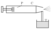
Drawn by us to help you understand the concept clearly, and verified to make sure it's accurate. For exams, practice from your textbook's own diagram.
What this figure shows. A tube T is shown with its lower end dipped into a reservoir of liquid, and a piston P inside a cylinder C positioned to blow a fast stream of air horizontally across the tube's upper, open tip. The fast-moving air passing over the tip lowers the pressure there (by Bernoulli's principle), so the liquid is drawn up the tube T from the reservoir below and, on reaching the top, is caught by and broken apart into very small droplets by the passing air stream, which carries them away as a fine spray — the working principle behind a sc …
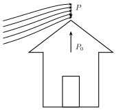
Drawn by us to help you understand the concept clearly, and verified to make sure it's accurate. For exams, practice from your textbook's own diagram.
What this figure shows. A house's roof is shown in cross-section, with high-speed, stormy wind blowing horizontally across its outer (upper) surface, while the air below the roof, inside the room, is shown as comparatively still and remaining at ordinary atmospheric pressure . The fast airflow above the roof lowers the pressure p there (by Bernoulli's principle, exactly as for the aerofoil in Fig. 2.37), so the pressure difference between the still air below () and the fast-moving air above (p) pushes the roof upward from underneath, lifting it off its supports and letting the wind blow it away — the same underlying mechanism as aerofoil lift, …