IV. Numerical Problems · Q12
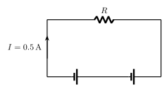
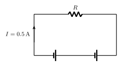
Q.Two cells, each of emf 5 V, are connected in series with an resistor and three parallel resistors of , and . Draw a circuit diagram for the above arrangement. Calculate
(i) the current drawn from the cells,
(ii) the current through each resistor.
Tamil Nadu DgeTextbookSubjectiveImportance★★★★★
43% · 44/102 Questions
You're viewing a preview — the full solution, concept, methods & PYQ mapping are locked.
Start your 14-day free trial to unlock the full solution →Step 1. Two 5 V cells in series give a combined emf of V (internal resistance not given, taken as negligible).
Step 2. The three parallel resistors combine as , so .
Step 3. This parallel combination is in series with the resistor, giving total circuit resistance .
Step 4 (i). The current drawn from the cells is A.
Step 5. The voltage across the parallel combination is V (this is the common voltage across all three parallel resistors). …
Unlock everything free for 14 days
- Full step-by-step solutions
- Concept-first explanations
- Methods, shortcuts & mistakes
- PYQ mapping + timed mock tests
Full access for 14 days. No credit card required.