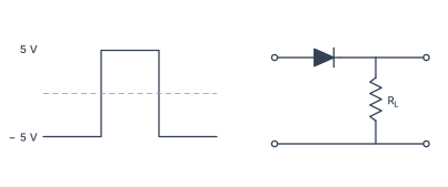
Q.Draw the output signal in a p-n junction diode when a square input signal of 10 V as shown in the figure is applied across it.
You're viewing a preview — the full solution, concept, methods & PYQ mapping are locked.
Start your 14-day free trial to unlock the full solution →A p-n junction diode acts as a one-way switch: it conducts only when forward-biased (p-side positive). For a 10 V square wave input, the output is a half-wave rectified square wave — only the positive half of the input appears across the load; the negative half is blocked, giving zero output.
Why this works — the core idea
A p-n junction diode is not a linear resistor. Its behaviour depends entirely on the polarity of the applied voltage:
- Forward bias (p-side at higher potential than n-side): the depletion region narrows, majority carriers flow freely, and the diode acts like a closed switch — current passes, and voltage appears across the load.
- Reverse bias (n-side at higher potential): the depletion region widens, only a tiny leakage current flows (negligible here), and the diode acts like an open switch — no current, no voltage across the load.
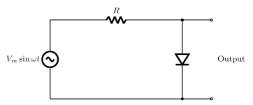
This property is called rectification: converting an alternating (or bidirectional) signal into a unidirectional one. The simplest circuit using this is a half-wave rectifier — a single diode in series with a load resistor.
A common mistake is to think the diode conducts during both halves of the square wave. It does not. The diode is polarity-sensitive: only the half-cycle that makes the p-side positive relative to the n-side will turn it on. The other half leaves the output at zero.
Step-by-step solution
1. Identify the circuit configuration
The problem shows a p-n junction diode connected in series with a load resistor . The square wave input of amplitude 10 V is applied across the series combination. The output voltage is taken across .
2. Understand the input signal
The input is a square wave that alternates between and with equal time periods. There is no zero-voltage interval — it jumps instantly from one extreme to the other.
3. Analyse the forward-bias half-cycle
When the input is , the p-side of the diode is at a higher potential than the n-side. This is forward bias. The diode turns on, and its voltage drop is small (≈0.7 V for silicon, but for an ideal diode we take it as zero). The entire input voltage appears across :
4. Analyse the reverse-bias half-cycle
When the input switches to , the p-side is now at a lower potential than the n-side. This is reverse bias. The diode turns off, behaving as an open circuit. No current flows through , so no voltage develops across it:
In a half-wave rectifier, the output is not the negative half of the input inverted — it is simply zero. The diode does not "flip" the negative part; it blocks it entirely.
5. Describe the output waveform …
Unlock everything free for 14 days
- Full step-by-step solutions
- Concept-first explanations
- Methods, shortcuts & mistakes
- PYQ mapping + timed mock tests
Full access for 14 days. No credit card required.