Question 35 of 54
Q.Draw a neat, labelled block diagram of a receiver for the detection of amplitude modulated wave.
Maharashtra MsbshseMaharashtra HSC (MSBSHSE) Board 2017Subjective· 2mImportance★★★★★
65% · 35/54 Questions
You're viewing a preview — the full solution, concept, methods & PYQ mapping are locked.
Start your 14-day free trial to unlock the full solution →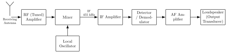
An AM receiver's block diagram takes the modulated signal from the antenna through RF and IF stages to a detector, then an audio amplifier, to recover and reproduce the original signal.
Block diagram description — receiver for detection of an amplitude-modulated (AM) wave:
- Antenna: picks up the transmitted AM radio wave.
- RF amplifier: amplifies the weak received radio-frequency signal and helps select the desired station's frequency band.
- Mixer + Local oscillator: the RF signal is mixed with a locally generated oscillator signal to produce a fixed, lower intermediate frequency (IF) signal (superheterodyne principle), which still carries the original modulation. …
Unlock everything free for 14 days
- Full step-by-step solutions
- Concept-first explanations
- Methods, shortcuts & mistakes
- PYQ mapping + timed mock tests
Full access for 14 days. No credit card required.