Question 36 of 54
Q.Explain with a neat diagram, how a p-n junction diode is used as a half wave rectifier.
Maharashtra MsbshseMaharashtra HSC (MSBSHSE) Board 2017Subjective· 3mImportance★★★★★
67% · 36/54 Questions
You're viewing a preview — the full solution, concept, methods & PYQ mapping are locked.
Start your 14-day free trial to unlock the full solution →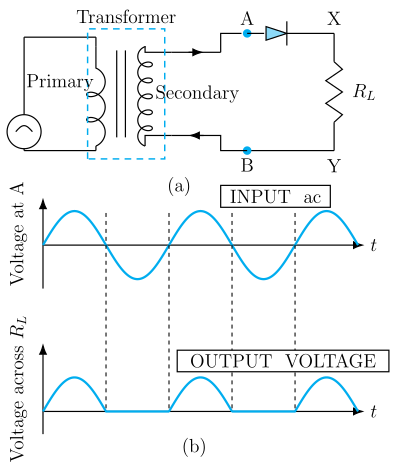
A single p-n junction diode conducts only during one half-cycle of the AC input, so it passes only that half — this is half-wave rectification.
Circuit: The AC input (from a step-down transformer secondary) is connected in series with a p-n junction diode and a load resistor ; the output is taken across .
Working:
- During the positive half-cycle of the input AC (p-side of the junction at higher potential), the diode is forward biased, offers low resistance, and conducts — current flows through , reproducing (a rectified version of) that half-cycle across the load.
- During the negative half-cycle, the diode becomes reverse biased, offers very high resistance, and does not conduct — no current flows through , so the output is (ideally) zero during this half. …
Unlock everything free for 14 days
- Full step-by-step solutions
- Concept-first explanations
- Methods, shortcuts & mistakes
- PYQ mapping + timed mock tests
Full access for 14 days. No credit card required.