Question 54 of 54
Q.With a neat circuit diagram, explain the working of a full wave rectifier. Draw input-output waveforms.
Maharashtra MsbshseMaharashtra HSC (MSBSHSE) Board 2026Subjective· 3mImportance★★★★★
100% · 54/54 Questions
You're viewing a preview — the full solution, concept, methods & PYQ mapping are locked.
Start your 14-day free trial to unlock the full solution →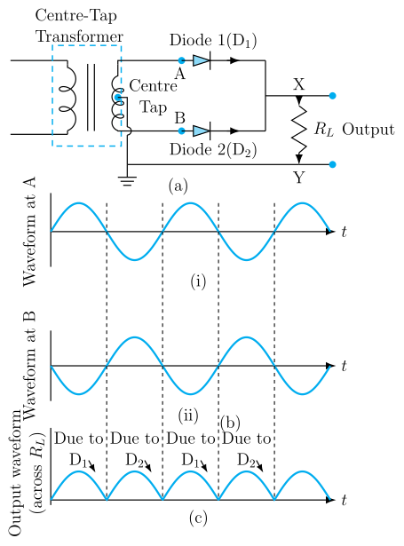
Two diodes, fed from a centre-tapped secondary, conduct on alternate half-cycles so that both halves of the AC input get converted into unidirectional current pulses through the load.
Circuit (centre-tap full wave rectifier), described: The secondary winding of a transformer is centre-tapped, with the centre tap grounded/connected to one end of the load resistor . The two outer ends of the secondary are connected to the anodes of two diodes (top) and (bottom); the cathodes of both diodes are joined together and connected to the other end of .
Working:
- During the positive half-cycle of the AC input, the top end of the secondary is positive with respect to the centre tap. This forward-biases (which conducts) while reverse-biasing (which is cut off). Current flows through centre tap, in a fixed direction through .
- During the negative half-cycle, the bottom end of the secondary is now positive with respect to the centre tap. This forward-biases (conducts) while is reverse-biased (cut off). Current again flows through in the same direction as before (via centre tap).
- Since current flows through the load in the same direction during both halves of the input cycle, the rectifier is called a full wave rectifier.
Waveforms: …
Unlock everything free for 14 days
- Full step-by-step solutions
- Concept-first explanations
- Methods, shortcuts & mistakes
- PYQ mapping + timed mock tests
Full access for 14 days. No credit card required.