Physics · Ch 12 — Electromagnetic Induction
Translational Motion of a Conductor
Translational Motion of a Conductor
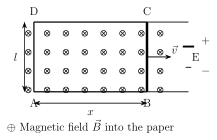
Consider a C-shaped conducting frame ABCD of wires, with a straight conducting rod BC of length l free to slide along the frame (parallel to AD) in a uniform magnetic field perpendicular to the plane of the frame. As BC slides outward with velocity , increasing the enclosed length x, the loop's area (and hence the flux linked with it) grows with time. By the flux rule, the magnitude of the induced emf is .
This same result follows independently from the microscopic Lorentz force on the charge carriers inside the moving rod BC. A charge q carried along with the rod experiences a force , which -- since and are both constant along BC -- is constant in magnitude and directed along the length of the rod (parallel to BC), and is zero everywhere else in the stationary part of the frame (where v = 0). As charge q traverses the rod's length l under this constant force, the work done is , where is the angle between and . Since emf is work done per unit charge, , which for the usual case of (i.e. , so ) gives the maximum value -- exactly matching the flux-rule result. …
Drawn by us to help you understand the concept clearly, and verified to make sure it's accurate. For exams, practice from your textbook's own diagram.
What this figure shows. Shows a C-shaped (three-sided, open-ended) conducting frame of wire, with corners labelled A, B, C, D, lying in a plane that also contains a uniform magnetic field drawn perpendicular to that plane (into or out of the page). A straight conducting rod BC of length l is drawn resting across the two parallel rails of the frame (sliding along, and staying parallel to, side AD), with a velocity arrow drawn along the rails' direction (the x-axis), showing BC being pushed outward so as to increase the separation x between BC and AD, thereby enlarging the frame's enclosed rectangular area ABCD as time passes. The figure establishes the geometry used to derive the sliding-rod motional emf both from the flux rule and from the Lorentz force on …