Physics · Ch 2 — Mechanical Properties of Fluids
Pascal's Law
Pascal's Law
Pascal's law states that the pressure applied at any point of an enclosed fluid at rest is transmitted equally and undiminished to every point of the fluid, and also to the walls of the container holding it, provided the effect of gravity on the fluid itself can be neglected.
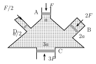
This can be demonstrated experimentally using a vessel with four arms, A, B, C and D, each fitted with a frictionless, water-tight piston, and the whole vessel filled with an incompressible fluid. If the cross-sectional areas of A, B, C and D are a, 2a, 3a and a/2 respectively, applying a force F on piston A creates a pressure in the fluid, and the other three pistons B, C and D are observed to move outward as a result. To hold each of these three pistons in its original position requires applying forces of 2F, 3F and F/2 to B, C and D respectively — which means the pressure on each of them, , , and , works out to exactly the same value p as on piston A. Since , this confirms directly that the pressure applied at A is transmitted equally and undiminished to every other part of the fluid and to the vessel walls, exactly as Pascal's law states.
Applications of Pascal's Law:
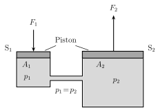
i) Hydraulic lift. A hydraulic lift is a machine, based directly on Pascal's law, used to lift a heavy object using only a comparatively small applied force. A tank of fluid is fitted with two pistons, a smaller one of cross-sectional area and a much larger one of cross-sectional area (). Applying a downward force on the smaller piston generates a pressure in the fluid, which by Pascal's law is transmitted undiminished to the larger piston , producing an upward force there of , i.e.
Since , the output force is very much larger than the input force — a heavy load can therefore be placed on and lifted up or lowered down simply by applying a much smaller force on . This is the working principle of a hydraulic lift. …
Drawn by us to help you understand the concept clearly, and verified to make sure it's accurate. For exams, practice from your textbook's own diagram.
Worked out. A vessel with four arms A, B, C and D, each fitted with a frictionless, water-tight piston, is shown filled with an incompressible fluid. The cross-sectional areas of A, B, C and D are a, 2a, 3a and a/2 respectively. When a force F is applied to piston A (creating pressure p = F/a in the fluid), the other three pistons are observed to move outward; to hold B, C and D in their original positions requires forces of exactly 2F, 3F and F/2 respectively — giving pressures pB = F/a, pC = F/a and pD = F/a on each of them, i.e. pB = pC = pD = p, the same pressure as on A. This experimentally confirms that the pressure applied at A is transmitted equally and undiminished to every other point of the fluid and …
Drawn by us to help you understand the concept clearly, and verified to make sure it's accurate. For exams, practice from your textbook's own diagram.
What this figure shows. A tank containing a fluid is shown fitted with two pistons: a smaller piston S1, of cross-sectional area A1, and a much larger piston S2, of cross-sectional area A2 (A2 ≫ A1), connected through the same enclosed body of fluid. A downward force F1 is applied to the smaller piston S1, generating a pressure p = F1/A1 in the fluid; by Pascal's law this pressure is transmitted undiminished to the larger piston S2, producing a much larger upward force F2 = pA2 = F1(A2/A1) on it. The figure shows how a heavy load placed on S2 can be raised or lowered by appl …
Drawn by us to help you understand the concept clearly, and verified to make sure it's accurate. For exams, practice from your textbook's own diagram.
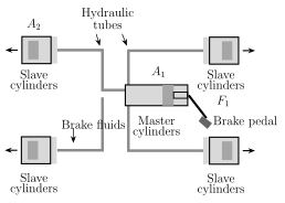
What this figure shows. A schematic of a vehicle's hydraulic brake system: a brake pedal is linked to a master cylinder with a small piston of cross-sectional area A1; tubing filled with brake fluid connects the master cylinder to a slave cylinder at each wheel, whose piston has a much larger cross-sectional area A2; the slave piston is shown pressing friction pads against a rotating brake disc connected to the wheel. Pressing the brake pedal pushes the master piston forward, generating pressure p = F1/A1 that is transmitted undiminished through the incompressible brake fluid to the slave cylinder, pushing its larger piston forward with a much larger force F2 = F1(A2/A1) — pressing the friction pads against the disc firmly enough to slow or stop the movi …