Physics · Ch 10 — Magnetic Fields due to Electric Current
Magnetic Force
Magnetic Force
The two-wire demonstration of Section 10.1 shows that a current-carrying wire experiences a force when placed in the magnetic field produced by a neighbouring current-carrying wire. To understand this force from first principles, it helps to go back to the most basic case: a single moving charge in an external magnetic field. Consider an electron, of charge , moving with velocity through a region where a magnetic field is present. Careful experiments (of exactly the sort suggested by Fig. 10.1) show that this charge experiences a magnetic force
and, more generally, for any charge (positive or negative),
If an electric field is ALSO present at the same location, the total force on the charge is the sum of the electric and magnetic contributions,
a combined expression known as the Lorentz force. Here is the familiar electrostatic force, and is the new, purely magnetic contribution this chapter is concerned with.
The cross product in carries several important physical consequences, all of which follow directly from the geometric properties of the cross product itself (Fig. 10.4). First, because a cross product of two vectors is always perpendicular to BOTH of them, is always perpendicular to -- which means at every instant, for ANY magnetic field. A force that is always perpendicular to the velocity does no work on the particle (since work requires a component of force ALONG the direction of displacement); the magnetic force can change the DIRECTION a charged particle moves in, but it can never change its SPEED, and hence never changes its kinetic energy either. This single fact underlies the circular and helical motion studied in the next two sections, and is also the reason a charged particle's kinetic energy stays fixed as it circulates inside a cyclotron between accelerating pushes from the electric field. Second, if the charge's velocity happens to be exactly PARALLEL to , the magnetic force is zero (since the angle between and is then , and ); this is the key fact behind the parallel-velocity component of helical motion (Section 10.4). Third, if the charge itself is stationary (), the force is zero even in the presence of an arbitrarily strong magnetic field () -- a magnetic field, unlike an electric field, exerts NO force at all on a charge at rest. …
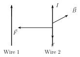
Drawn by us to help you understand the concept clearly, and verified to make sure it's accurate. For exams, practice from your textbook's own diagram.
What this figure shows. Two parallel straight wires (wire 1 and wire 2) carry current, with the magnetic field produced by wire 1, at the location of wire 2, drawn directed INTO the plane of the paper (shown by a cross symbol along wire 2's length). The conduction electrons in wire 2 are shown flowing in a direction opposite to the conventional current in wire 2 (since current is due to negatively charged electrons), and a force arrow is drawn on wire 2, pointing horizontally TOWARDS wire 1 -- illustrating, via the Lorentz force on the moving electrons, exactly how the attraction/repulsion of Fig. 10.1 arises from the magnetic field one current-carr …
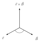
Drawn by us to help you understand the concept clearly, and verified to make sure it's accurate. For exams, practice from your textbook's own diagram.
What this figure shows. A three-dimensional vector diagram showing a velocity vector and a magnetic field vector drawn from a common origin, at some general angle to each other, together spanning a plane. A third vector, the cross product (and hence the direction of the resulting force on a positive charge), is drawn PERPENDICULAR to this plane, following the right-hand rule for a vector cross product (fingers point along , curl towards , thumb gives ). The figure exists purely to fix this vector-geometry convention: F is always normal to the …
Worked out. A negatively charged particle travels with velocity through a uniform magnetic field in three different situations (a), (b), (c), each drawn with a different relative orientation of v and B; the question asks for the direction of the magnetic force in each case. In (a), works out to the positive y direction, but since the charge is NEGATIVE, is in the positive y direction (the example text states this directly, applying the sign of the charge to flip -- or in this stated case, confirm -- the direction of ). In (b), is along the positive x direction, so (for the negative charge) is opposite, i.e. along negative x. In (c), and are exactly anti-parallel (angle ), and since , regardless of …