Physics · Ch 10 — Magnetic Fields due to Electric Current
Cyclotron Accelerator
Cyclotron Accelerator
Particle accelerators -- machines that use electric and/or magnetic fields to bring charged particles up to very high energies (from a few MeV to several GeV) -- are essential tools both for fundamental research into the structure of matter, and, in some cases, for practical applications such as the medical treatment of certain tumours. The cyclotron, invented by Lawrence and Livingston in 1934 specifically to study nuclear structure, was one of the earliest and most influential such machines, and it works by combining BOTH electric and magnetic fields, applied in mutually perpendicular directions (hence sometimes called "crossed fields"): the magnetic field's job is to bend the charged particle's path into a (growing) circular arc, using exactly the cyclotron-formula physics of Section 10.3, while the electric field's job is to accelerate the particle, giving it a burst of extra energy each time it crosses a particular gap. A key fact makes this combination work: the FREQUENCY at which a charged particle revolves in a magnetic field, , does not depend on its energy at all (only on its charge, mass and the field strength) -- so even as the particle's energy (and hence orbital radius) keeps growing throughout the acceleration process, the TIME it takes to complete each half-revolution stays exactly the same, letting a fixed-frequency alternating voltage keep pace with it.
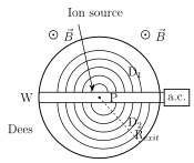
Physically, the cyclotron consists of two hollow, semicircular disc-like metal chambers, called Dees (D1 and D2, from their D-like shape), placed with a narrow gap between them, the whole assembly sitting inside a uniform magnetic field B applied perpendicular to the plane of the Dees (produced, in practice, by an electromagnet capable of fields up to about 1.5 T). An alternating voltage, of amplitude up to around 10,000 V and frequency around 10 MHz, is applied across the gap between the two Dees. Positive ions are produced (by a gas-ionising source) at a point O in the gap between the Dees, and the electric field across the gap gives the ion its first push of acceleration. Once inside a Dee, the ion is shielded from the electric field entirely (the Dees themselves are hollow conducting chambers, so no field penetrates inside), and it simply travels a semicircular arc under the magnetic field's influence alone, at whatever speed it currently has. When it re-emerges into the gap on the other side, the alternating voltage's polarity has, by design, reversed in the meantime, so the ion is accelerated again -- gaining more energy, and hence tracing a slightly LARGER semicircle in the next Dee. Repeating this process again and again causes the ion's path to spiral steadily outward (Fig. 10.6), gaining energy at every crossing of the gap, until it reaches the outer edge of the Dees, where a deflecting field extracts it through an exit slit.
Quantitatively, using the cyclotron formula (Eq. 10.7) for an ion of charge at radius : the time for one full semicircular pass is , i.e. the period of a FULL revolution is , entirely independent of or -- exactly the fact that makes the fixed-frequency accelerating voltage possible. The corresponding cyclotron frequency is
…
Drawn by us to help you understand the concept clearly, and verified to make sure it's accurate. For exams, practice from your textbook's own diagram.
What this figure shows. A top-down schematic of a cyclotron: two D-shaped hollow metal chambers (dees), labelled D1 and D2, are placed side by side with a narrow gap between their straight edges, together forming a near-complete circle. A uniform magnetic field is shown perpendicular to the plane of the Ds (represented by dots, indicating the field comes OUT of the plane of the paper). An ion source is marked at a point P at the centre, in the gap between the two Ds. The ion's trajectory is drawn as an outward-expanding SPIRAL of semicircular arcs alternating between the two Ds, each successive semicircle of larger radius than the last, terminating at an exit slit near the outer edge of the assembly; an alternating voltage source is shown connected across the gap betw …