Physics · Ch 10 — Magnetic Fields due to Electric Current
Moving Coil Galvanometer
Moving Coil Galvanometer
A direct and historically important practical application of the torque formula (Section 10.7) is the moving coil galvanometer -- an instrument for measuring small electric currents (or, with an appropriate series/shunt resistance, voltages), and the working principle behind analog ammeters and voltmeters.
The galvanometer's coil, of turns and area , is mounted (either suspended from a fine fibre, or pivoted on jewelled bearings) so that it is free to rotate about a fixed axis, and is placed within a RADIAL magnetic field -- a field arrangement, produced using curved magnet pole-faces together with a soft-iron cylindrical core inside the coil, engineered specifically so that the field lines always point straight in towards the core, and hence remain PERPENDICULAR to the plane of the coil, no matter what angular position the coil has rotated to (Fig. 10.13). This radial-field design is the whole point of the instrument's construction: because the field is always perpendicular to the coil's plane, the angle between the coil's normal and is ALWAYS , so identically, REGARDLESS of how far the coil has rotated. The deflecting torque due to the current is therefore always simply
(with no factor to complicate matters), directly proportional to the current flowing through the coil, for any angular position.
This deflecting torque is opposed by a RESTORING torque supplied by a hairspring attached to the coil's suspension, whose restoring torque is proportional to the angular deflection from the coil's rest position, i.e. , where is the spring's torsional constant. The coil settles into a steady EQUILIBRIUM deflection where these two torques exactly balance:
…
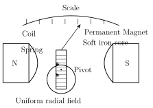
Drawn by us to help you understand the concept clearly, and verified to make sure it's accurate. For exams, practice from your textbook's own diagram.
What this figure shows. A cross-sectional diagram of a moving coil galvanometer: a rectangular coil of several turns of wire is shown mounted around a fixed cylindrical soft-iron core, with curved pole faces of a permanent magnet (marked N and S) surrounding the coil on either side so as to produce a magnetic field that is always RADIAL (pointing straight in towards the core) at the coil's location, regardless of the coil's angular position. A hairspring is shown attached to the coil's suspension/pivot, providing the restoring torque that opposes the coil's magnetic-torque-driven rotation and brings it to a steady equilibrium …