Q.A. State the principle on which transformer works. Explain its working with construction. Derive an expression for the ratio of e.m.f.s and currents in terms of the number of turns in the primary and secondary coil.
B. A conductor of any shape, having area 40 cm², placed in air is uniformly charged with a charge 0.2 μC. Determine the electric intensity at a point just outside its surface. Also find the mechanical force per unit area of the charged conductor. [ S.I. units]
OR
A. With the help of a neat labelled diagram, describe the Geiger-Marsden experiment. What is mass defect?
B. The photoelectric work function for a metal surface is 2.3 eV. If light of wavelength 6800 Å is incident on the surface of the metal, find the threshold frequency and incident frequency. Will there be an emission of photoelectrons or not? [Velocity of light m/s, Planck's constant Js]
You're viewing a preview — the full solution, concept, methods & PYQ mapping are locked.
Start your 14-day free trial to unlock the full solution →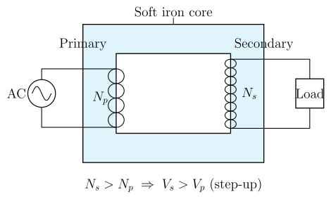
A transformer transfers energy between coils via a shared changing flux (mutual induction); separately, use and electrostatic pressure for the charged conductor.
A. Transformer — principle, construction, working, and turns ratio
Principle: A transformer works on the principle of mutual electromagnetic induction — when the current (and hence the magnetic flux) in one coil changes, an e.m.f. is induced in a neighbouring coil that is magnetically linked to it.
Construction: A transformer consists of two coils of insulated copper wire, called the primary (connected to the AC input/source, turns) and the secondary (connected to the load, turns), wound on a common laminated soft-iron core. The laminated core (thin sheets insulated from each other) concentrates and guides the magnetic flux from the primary to the secondary while minimising energy losses due to eddy currents.
Working: When an alternating voltage is applied to the primary, it drives an alternating current, which sets up an alternating magnetic flux in the core. Since the secondary is wound on the same core, this same changing flux links the secondary coil too, inducing an alternating e.m.f. in it (by Faraday's law), which in turn drives a current through the load connected to the secondary.
Derivation of the turns ratio: Let be the flux linked per turn (common to both coils, assuming no flux leakage). By Faraday's law, the e.m.f. induced per turn is . So:
Dividing:
For an ideal transformer (no losses), input power = output power:
Combining: …
Unlock everything free for 14 days
- Full step-by-step solutions
- Concept-first explanations
- Methods, shortcuts & mistakes
- PYQ mapping + timed mock tests
Full access for 14 days. No credit card required.