Physics · Ch 10 — Magnetic Fields due to Electric Current
Solenoid
Solenoid
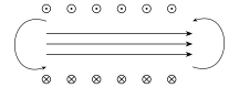
Consider a long, closely-wound helical coil of conducting wire -- a SOLENOID -- with its diameter assumed much smaller than its length (Fig. 10.24). Experimentally (and as confirmed by the Ampere's-law derivation below), the magnetic field lines INSIDE such a solenoid, sufficiently far from its two ends, run parallel to the solenoid's own axis and are closely, uniformly spaced -- indicating a strong, essentially UNIFORM field there -- while OUTSIDE the solenoid the field lines spread out widely and are very sparse, indicating a comparatively very weak field. In the idealised limit of an INFINITELY long, perfectly and tightly wound solenoid, this qualitative picture becomes exact: the field inside is perfectly uniform, and the field outside is exactly zero everywhere.
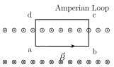
To find the field inside such an ideal solenoid using Ampere's law, choose a RECTANGULAR Amperian loop (Fig. 10.25), with one side, say (of length ), lying entirely INSIDE the solenoid, parallel to its axis; the opposite side lying entirely OUTSIDE the solenoid; and the remaining two sides and each crossing from inside to outside, PERPENDICULAR to the solenoid's axis. Evaluating around this loop, side by side: along (inside, parallel to ), the contribution is simply ; along (outside, where for an ideal solenoid), the contribution is exactly zero; and along the two perpendicular sides and , (wherever it is nonzero, i.e. on the portion inside the solenoid) is PERPENDICULAR to , so there too. So the ENTIRE line integral reduces to just the one nonzero contribution from side :
Setting this equal to times the net current ENCLOSED by the loop: if there are turns per unit length of the solenoid, each carrying current , then the loop (of length along the solenoid's axis) encloses a net current of (that is, individual turns, each contributing current ). Ampere's law then gives
…
Drawn by us to help you understand the concept clearly, and verified to make sure it's accurate. For exams, practice from your textbook's own diagram.
What this figure shows. A cross-sectional schematic of a solenoid -- a long, tightly and closely wound helical coil of conducting wire, drawn much longer than it is wide (its diameter much smaller than its length) -- with the resulting magnetic FIELD LINES sketched running along the solenoid's axis, packed closely together and parallel INSIDE the coil (indicating a strong, uniform field there), and spreading out widely and sparsely OUTSIDE the coil (indicating a comparatively very weak external field), closely resembling the field of a bar magnet with …
Drawn by us to help you understand the concept clearly, and verified to make sure it's accurate. For exams, practice from your textbook's own diagram.
What this figure shows. A cross-sectional view of part of a long, IDEAL solenoid is shown, with the wire's cross section drawn as a SQUARE (an idealisation, with dots (.) marking turns where current comes OUT of the plane of the paper on one side of the solenoid, and crosses (x) marking turns where current goes INTO the plane on the other side). A rectangular Amperian loop abcd is drawn straddling the solenoid's wall: side ab lies entirely INSIDE the solenoid (parallel to the axis, of length L), side bc crosses from inside to outside (perpendicular to the axis, hence perpendicular to the internal B), side cd lies entirely OUTSIDE the solenoid (where B is taken as zero), and side da again crosses perpendicular to the axis back to the starting point -- this specific rectangular-loop choice is exactly what makes three of the four sides' contr …
Worked out. A solenoid of length 25 cm has an inner radius of 1 cm and is wound with 250 turns of copper wire, carrying a current of 3 A; the magnitude of the magnetic field inside the solenoid is required. The number of turns per unit length is turns/m, and applying directly: , which evaluates to T -- note that the solenoid's radius (1 cm) plays no role at all in the final answer, exactly as the ideal-solenoid der …