Physics · Ch 10 — Magnetic Fields due to Electric Current
Straight Wire
Straight Wire
Consider a straight wire of length (Fig. 10.8), carrying a steady current , placed in an external magnetic field applied perpendicular to the wire. Let be the (common) drift velocity of the conduction electrons inside the wire. In a time , the total charge that flows across any cross-section of the wire is, by the definition of current, ; and since the electrons travel with drift speed , this same charge can also be related to the length of wire the electrons traverse in that time, giving
(using , the time for an electron to drift the full length of the segment). Now apply the single-charge Lorentz force law (Section 10.2) to this "lumped" charge , treated as moving with the drift velocity through the field :
where the reflects the given condition that is applied perpendicular to the wire, and the two factors of conveniently cancel -- the DRIFT SPEED itself drops out of the final formula entirely, leaving the force expressed purely in terms of the macroscopic, directly-measurable current . This is therefore the magnetic force on a straight segment of wire, of length , carrying current , in a field applied exactly perpendicular to the wire:
More generally, if is NOT necessarily perpendicular to the wire, the same derivation (carried through with the general angle between the current direction and ) gives the fully vectorial version of this force law. Defining a length vector directed ALONG the wire, in the sense of the current flow, with magnitude equal to the wire's length:
…
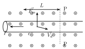
Drawn by us to help you understand the concept clearly, and verified to make sure it's accurate. For exams, practice from your textbook's own diagram.
What this figure shows. A straight segment of current-carrying wire of length L is shown with its conduction electrons drifting with drift velocity (drawn opposite to the direction of conventional current flow, since electrons are negatively charged). An external uniform magnetic field is applied perpendicular to the wire, with its field lines drawn coming OUT of the plane of the paper (dots along the length of the wire). A resultant force arrow is drawn pointing UPWARD on the wire (perpendicular to both the wire and to B), illustrating that the sideways push experienced by the individual drifting electrons adds up, over the whole segment, to a single net sideways force on the wire it …