Solved Examples · Example 4
Q.Calculate the frequency and feedback factor of the circuit shown below.
Karnataka PUCTextbookNumericImportance★★★★★est
22% · 19/86 Questions
You're viewing a preview — the full solution, concept, methods & PYQ mapping are locked.
Start your 14-day free trial to unlock the full solution →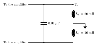
[!TLDR]
With and , ; the feedback factor is .
The shown network is the Hartley feedback tank: a single capacitor across a centre-tapped inductor. The feedback voltage is developed across and the output across , which is why the feedback factor is the inductance ratio . The frequency is the tank resonance with .
Step 1 — total inductance: . …
Unlock everything free for 14 days
- Full step-by-step solutions
- Concept-first explanations
- Methods, shortcuts & mistakes
- PYQ mapping + timed mock tests
Full access for 14 days. No credit card required.